00194614-08 Trainingsdoku. SG X-Serie_X4i SW70x (AL2)_EN.pdf - 第477页
MTC2 MTC2 Calibration and Settings Adjustments Lifting Axes 477 Student Guide SIPLACE X-Serie and X4I SW70x (AL2) Checking an d setting the b elt tension Checking and setting the belt tension ► Carry out the relevant pre…
MTC2
Adjustments Lifting Axes MTC2 Calibration and Settings
Student Guide SIPLACE X-Serie and X4I SW70x (AL2) 476
▪ 1 set of Allen keys
▪ 1 set of open-ended wrenches
Preparat ions
Preparations
► Empty the MTC2 completely (see the User Manual).
► Move the lifting axis into its bottom position.
► Remove the left cover in front of the electronics board and the covers on the right and the left in front
of the Masterdrives.
► Switch the motor protection switch off (see ).
► To relieve the tension the toothed belts, loosen the brake on the servo motor in the following way to
rest the lifting axis on the buffer:
⇨ Check whether the MTC2 has been switched off and is isolated from the power supply.
⇨ Disconnect the terminal connector for the external signals from the lifting axis master drive.
⇨ Move the cable from Pin 3 to Pin 1.
⇨ Attach the connector.
⇨ Connect the MTC2 to the power supply and switch it on.
⇨ The lifting axis audibly moves a distance of a few mm up to the buffer.
► Check that the lifting axis is actually at its end position.
► Reconnect the cable as it was originally in the following way:
⇨ Switch off the MTC2 and isolate it from the power supply.
⇨ Disconnect the terminal connector for the external signals from the lifting axis master drive.
⇨ Move the cable from Pin 1 to Pin 3.
⇨ Attach the connector.
► Switch the motor protection switch on.
► Attach the covers.
► Undock the MTC2 from the SIPLACE station (see User Manual).
► Crank up the MTC2 in a clockwise direction until it stops.
See also
13.3.3.1.1 Tools and Equipment [ ➙ 475]
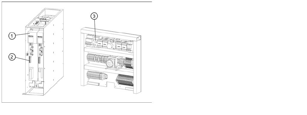
Connections to the Masterdrives of the lifting axes
Legend
1. Masterdrive, lifting axis (shown here for tower 1)
2. Connection terminal for external signals
3. Motor protection switch on the electronics board
MTC2
MTC2 Calibration and Settings Adjustments Lifting Axes
477 Student Guide SIPLACE X-Serie and X4I SW70x (AL2)
Checking an d setting the b elt tension
Checking and setting the belt tension
► Carry out the relevant preparations (see "13.3.3.1.2 Preparations" [ ➙ 476]).
► Measure the belt tension with the belt frequency measuring device in the following way:
⇨ Find the holes for the measurement head of the belt frequency measuring device on the lifting
axis. Two holes are provided for each of the dual toothed belts (see "13.3.3 Adjustments Lifting
Axes" [ ➙ 475]).
⇨ Attach the toothed belt tension stickers (Part no. 00370691-0) onto the belts in this area.
⇨ Cause the belts to oscillate and measure their frequency.
⇨ You must set the belt tension if the measured frequency deviates from the nominal value [(200Hz
± 5Hz),(210Hz ± 5Hz) see note above]:
⇨ Turn the adjusting screws as far as they will go. Before doing this you will need to loosen the lock
nuts.
⇨ Loosen the four lock screws on the mounting plate of the motor.
⇨ Use the two adjusting screws to raise the belt tension (by turning in a clockwise direction) or
lower it (by turning in an anticlockwise direction), until the nominal frequency is achieved. Tighten
the lock nuts each time you measure the belt tension.
⇨ Firmly tighten the clamping screws and varnish them with red screw locking varnish.
⇨ Check the belt tension again.
⇨ Remove the belt tension stickers.
► Dock the MTC2 onto the SIPLACE station (see the User Manual).
► Check the zero offset of the lifting axis (see "13.3.2.1 Lifting axis" [ ➙ 467]), if you have changed the
belt tension.
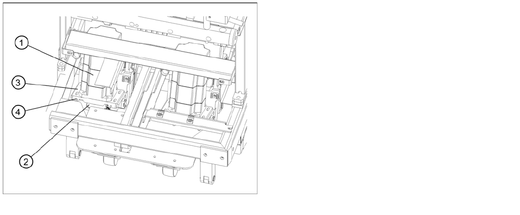
Setting the belt tension
Legend
1. Servo motor of the lifting axis (shown here for tower
2)
2. Dual toothed belt (shown here for tower 2)
3. Mounting plate with clamping screws (shown here for
tower 2)
4. Adjusting screws with lock nuts (shown here for tower
2)
MTC2
Adjustments Lifting Axes MTC2 Calibration and Settings
Student Guide SIPLACE X-Serie and X4I SW70x (AL2) 478
Guide R ails and Stopper B ars
13.3.3.2 Guide Rails and Stopper Bars
Tools and accessories
Tools and accessories
▪ 1 set of Allen keys
Preparat ions
Preparations
► Move the lifting axis into the refill position for cassette 1 and completely set up the MTC2 with empty
cassettes (see User Manual).
► Set up every cassette with an empty WTC in the bottom and in the top level.
Checking an d setting th e guide rails, top
Checking and setting the guide rails, top
► Manually open the WTC interlock for each WTC which has been set up and check that the WTC can
be pulled out approx. 0.5 to 1mm up to the closed guide rail. When closing the WTC interlock, the
WTC must automatically click into place.
► Open the guide rail. When closing the guide rail, use a WTC which has been pulled out to check
either:
⇨ that the WTC engages in the WTC interlock again on its own or
⇨ that the guide rail cannot be closed.
► Set the position of the guide rail (by moving it in its fixing holes), if the behavior described above is
not observed.
Checking an d setting the s topper bars, top
Checking and setting the stopper bars, top
► Manually open the side interlock (leaf springs) for each WTC and check that the WTC can be pushed
through approx. 0.5 to 1mm up to the stopper bar. When closing the interlock, the WTC must click
into place automatically.
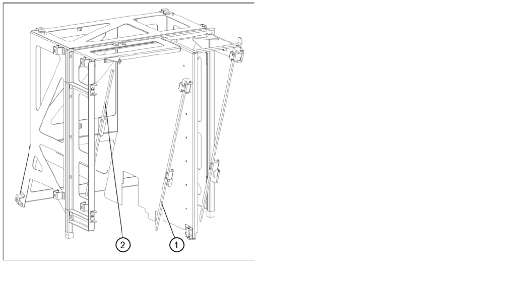
Guide rails and stopper bars in the upper frame
Legend
1. Guide rail (shown here for tower 1)
2. Stopper bar (shown here for tower 1)