00194614-08 Trainingsdoku. SG X-Serie_X4i SW70x (AL2)_EN.pdf - 第479页
MTC2 MTC2 Calibration and Settings Adjustments Lifting Axes 479 Student Guide SIPLACE X-Serie and X4I SW70x (AL2) ► Set the position of the stopper bar (by mov ing it in its fixing holes), if the behavior described above…
MTC2
Adjustments Lifting Axes MTC2 Calibration and Settings
Student Guide SIPLACE X-Serie and X4I SW70x (AL2) 478
Guide R ails and Stopper B ars
13.3.3.2 Guide Rails and Stopper Bars
Tools and accessories
Tools and accessories
▪ 1 set of Allen keys
Preparat ions
Preparations
► Move the lifting axis into the refill position for cassette 1 and completely set up the MTC2 with empty
cassettes (see User Manual).
► Set up every cassette with an empty WTC in the bottom and in the top level.
Checking an d setting th e guide rails, top
Checking and setting the guide rails, top
► Manually open the WTC interlock for each WTC which has been set up and check that the WTC can
be pulled out approx. 0.5 to 1mm up to the closed guide rail. When closing the WTC interlock, the
WTC must automatically click into place.
► Open the guide rail. When closing the guide rail, use a WTC which has been pulled out to check
either:
⇨ that the WTC engages in the WTC interlock again on its own or
⇨ that the guide rail cannot be closed.
► Set the position of the guide rail (by moving it in its fixing holes), if the behavior described above is
not observed.
Checking an d setting the s topper bars, top
Checking and setting the stopper bars, top
► Manually open the side interlock (leaf springs) for each WTC and check that the WTC can be pushed
through approx. 0.5 to 1mm up to the stopper bar. When closing the interlock, the WTC must click
into place automatically.
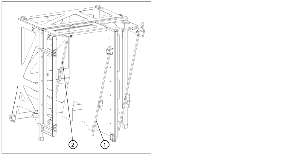
Guide rails and stopper bars in the upper frame
Legend
1. Guide rail (shown here for tower 1)
2. Stopper bar (shown here for tower 1)
MTC2
MTC2 Calibration and Settings Adjustments Lifting Axes
479 Student Guide SIPLACE X-Serie and X4I SW70x (AL2)
► Set the position of the stopper bar (by moving it in its fixing holes), if the behavior described above
is not observed. If necessary, remove the covers behind the doors.
Check on tower 1 that a WTC XL with 25 mm-high components can be transported without colliding
with the stopper bar. If necessary, correct the position of the stopper bar.
Checking and setting the stopper bars, bottom
Checking and setting the stopper bars, bottom
Cassette g uide rails
13.3.3.3 Cassette guide rails
Tools and Equipment
Tools and Equipment
▪ 1 set of Allen keys
Preparat ions
Preparations
► Empty the MTC2 completely (see the User Manual).
► Prepare an empty cassette XL.
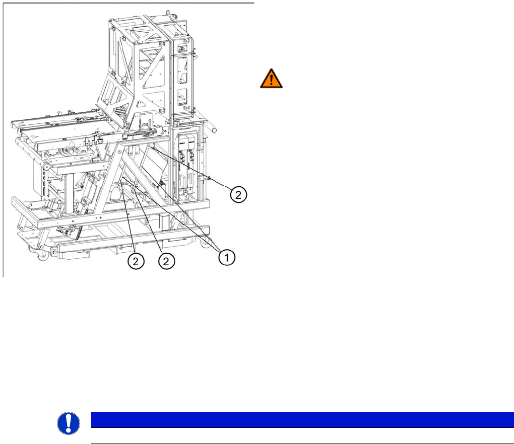
Guide rails, bottom
► Move the doors fully down
► Remove the side covers
► Set the position of the guide rails until they are
approx. 0.5 through 1mm away from the WTCs.
WARNING! The stopper bar and guide rail must
under no circumstances touch the WTCs!
Legend
1. Guide rails
2. Fastening screws
NOTICE
An empty cassette is needed to set the cassette guide rails.
MTC2
Adjustments Lifting Axes MTC2 Calibration and Settings
Student Guide SIPLACE X-Serie and X4I SW70x (AL2) 480
Setting the cassette g uide rails
Setting the cassette guide rails
► Move the lifting axis into the refill position for cassette 1-> check the zero offset.
► Loosen the securing screws on both cassette guide rails.
► Tighten the securing screws of the inner cassette guide rail at the position in which the cassette can
still be inserted into the tower smoothly.
► Position the second cassette guide rail by means of the cassette parallel to the first cassette, so that
the cassette can be moved easily but without any lateral play. Tighten the securing screws here as
well.
► Check the setting of the other refill positions. -> "Check the refill positions“). If necessary, correct the
position of the cassette guide rails which has been set.
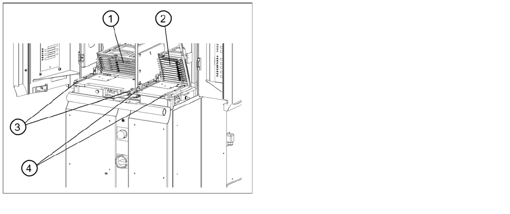
Setting the cassette guide rails
Legend
1. Cassette XL in the refill position for tower 1
2. Cassette in the refill position for tower 2
3. Cassette guide rails for tower 1
4. Cassette guide rails for tower 2