00194614-08 Trainingsdoku. SG X-Serie_X4i SW70x (AL2)_EN.pdf - 第481页
MTC2 MTC2 Calibration and Settings Adjustments feed axes 481 Student Guide SIPLACE X-Serie and X4I SW70x (AL2) Adjustments feed axes 13.3.4 Adjustments feed axes Overview of the feed axes (cover plates and b elt covers r…
MTC2
Adjustments Lifting Axes MTC2 Calibration and Settings
Student Guide SIPLACE X-Serie and X4I SW70x (AL2) 480
Setting the cassette g uide rails
Setting the cassette guide rails
► Move the lifting axis into the refill position for cassette 1-> check the zero offset.
► Loosen the securing screws on both cassette guide rails.
► Tighten the securing screws of the inner cassette guide rail at the position in which the cassette can
still be inserted into the tower smoothly.
► Position the second cassette guide rail by means of the cassette parallel to the first cassette, so that
the cassette can be moved easily but without any lateral play. Tighten the securing screws here as
well.
► Check the setting of the other refill positions. -> "Check the refill positions“). If necessary, correct the
position of the cassette guide rails which has been set.
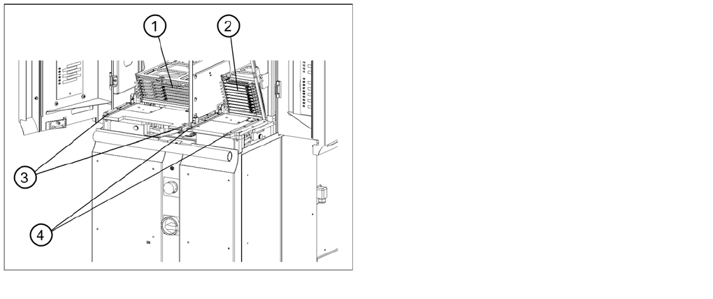
Setting the cassette guide rails
Legend
1. Cassette XL in the refill position for tower 1
2. Cassette in the refill position for tower 2
3. Cassette guide rails for tower 1
4. Cassette guide rails for tower 2
MTC2
MTC2 Calibration and Settings Adjustments feed axes
481 Student Guide SIPLACE X-Serie and X4I SW70x (AL2)
Adjustments feed axes
13.3.4 Adjustments feed axes
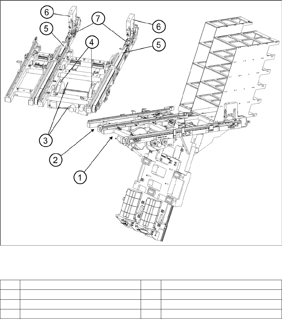
Overview of the feed axes (cover plates and belt covers removed)
Legend
Belt tensio n
13.3.4.1 Belt tension
Tools and Equipment
Tools and Equipment
▪ Belt frequency measurement device (inductive)
▪ 2 belt tension strips
▪ 1 set of Allen keys
▪ 1 set of open-ended wrenches
1 Feed axis, tower 1 5 Toothed belt
2 Feed axis, tower 2 6 Disengaging mechanisms
3 Servo motors of the feed axes 7 Driver
4 Drive belt
MTC2
Adjustments feed axes MTC2 Calibration and Settings
Student Guide SIPLACE X-Serie and X4I SW70x (AL2) 482
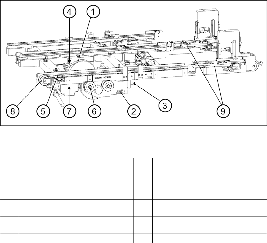
Checking and setting the belt tension
Legend
Preparat ions
Preparations
► Empty the MTC2 completely (see the User Manual).
► Undock the MTC2 from the SIPLACE station (see User Manual).
► Remove both cover plates between the rails of the feed axes.
Checking an d Setting the Driv e Belt
Checking and Setting the Drive Belt
► Carry out the relevant preparations (see "13.3.3.1.2 Preparations" [ ➙ 476]).
► Measure the belt tension with the belt frequency measuring device in the following way:
► Make the drive belt oscillate and measure the frequency in the middle of the sloping surface,
between the motor axis and the belt wheel (for the measuring point, see"13.3.3.1.1 Tools and
Equipment" [ ➙ 475]).
► You must set the belt tension if the measured frequency deviates from the nominal value (120 Hz ±
5 Hz):
► Turn the adjusting screw of the drive belt as far as it will go. Before doing this you will need to loosen
the lock nut.
► Loosen the two clamping screws on the mounting block of the motor.
► Use the adjusting screw to raise the belt tension (by turning in a clockwise direction) or lower it (by
turning in an anticlockwise direction), until the nominal frequency is achieved. Tighten the lock nuts
each time you measure the belt tension.
1 Drive belt (shown here for tower 2) 6 Eccentric axle of toothed belt with clamping
screw and flats for setting (shown here for
tower 1)
2 Motor mounting block with clamping
screws (shown here for tower 1)
7 Measuring point, toothed belt (shown here
for tower 1)
3 Adjustment screw, drive belt (shown here
for tower 1)
8 Outer deflection roll (shown here for tower
1)
4 Measuring point, drive belt (shown here for
tower 2)
9 Driver
5 Toothed belt (shown here for tower 1)