00194614-08 Trainingsdoku. SG X-Serie_X4i SW70x (AL2)_EN.pdf - 第55页
Overview Overview of Components Axis Unit with A364 55 Student Guide SIPLACE X-Serie and X4I SW70x (AL2) Axis Unit with A3 64 3.2.5 Axis Unit with A 364 The axis unit contains the servo boards, axis c ontroller boards , …
Overview
Sectors 1 - 4 Overview of Components
Student Guide SIPLACE X-Serie and X4I SW70x (AL2) 54
Sectors 1 - 4
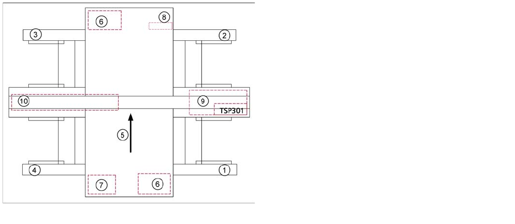
3.2.3 Sectors 1 - 4
Sector 1/3:
▪ Connector module for the safety circuit and the Start/Stop button
▪ Boards for single-handed operation of changeover tables for location 1/4 or sector 3 for locations 3/2.
▪ Signaling circuit for the hoods
Sector 2 (main distributor):
▪ CAN I/O module with the 1 wire module (1 wire is only used for the temperature sensors.)
▪ DC distributor for illumination of cameras in placement area 2
▪ Main distributor (connector module)
▪ Terminals X1qa (GND, +5 V, +15 V, -15 V, +24 V, Start/Stop signal, covers, emergency STOP
signal, SW release signal)
▪ Connector module for the safety circuit and Start/Stop button
Sector 4 (subdistributor):
▪ CAN I/O module with the 1 wire module (1 wire is only used for the temperature sensors.)
▪ DC distributor for illumination of cameras in placement area 1
▪ Intermediate distributor (connector module)
▪ Terminals X1ra (GND, +5 V, +15 V, -15 V, +24 V, Start/Stop signal, covers, emergency STOP
signal, ...)
▪ Connector module for the safety circuit and Start/Stop button
▪ Relay and fuse for the hood fans (24 V)
Computer Unit with BoxPC
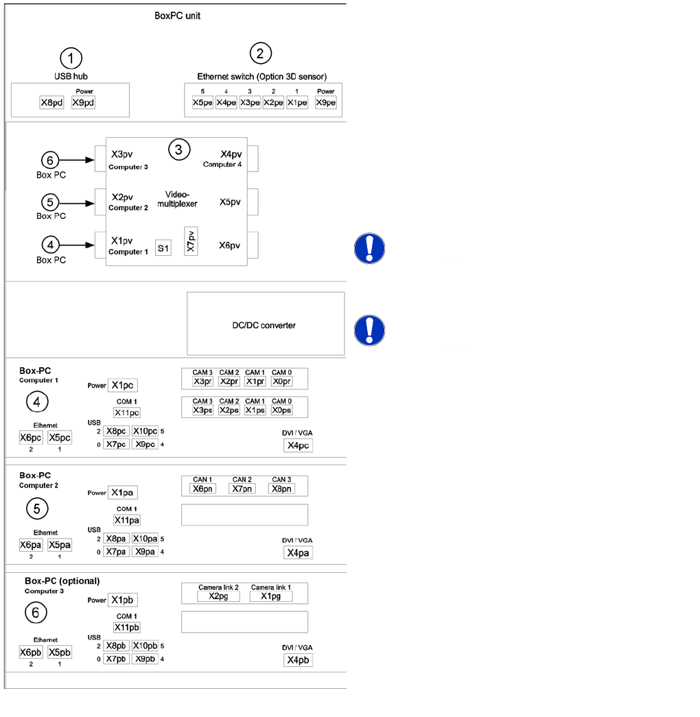
3.2.4 Computer Unit with BoxPC
In placement machines from X-series MA. No. 600 and X4I have BoxPCs in the computer unit.
Up to 3 BoxPCs will be installed, depending on the machine type and configuration.
Overview of sectors 1 - 4
Legend
1. Sector 1
2. Sector 2
3. Sector 3
4. Sector 4
5. Transport direction
6. Axis unit 1/2
7. Computer unit
8. DC/DC converter FCU (feeder control unit)
9. Pneumatic unit with conveyor control
10. Power supply unit
Overview
Overview of Components Axis Unit with A364
55 Student Guide SIPLACE X-Serie and X4I SW70x (AL2)
Axis Unit with A364
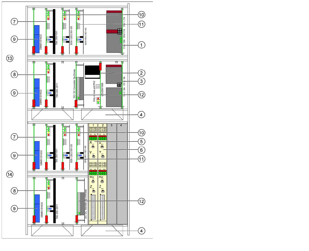
3.2.5 Axis Unit with A364
The axis unit contains the servo boards, axis controller boards, power supplies (+/-15V,+5V) and ballast
circuit. The flexible axis unit is equipped with the correct servo and axis boards for the machine type and
head configuration concerned. Depending on the machine type, there will be either one or two axis units
in the machine.
See also
12.9 Slots in the Axis Unit [ ➙ 428]
Computer unit with BoxPC [00351894-xx]
Position of assemblies in the computer unit
1. 4 port USB hub 2.0
2. Ethernet switch (only for optional 3D sensor)
3. Video multiplexer
4. Computer 1:
Vision computer (from SW 70x)
5. Computer 2:
Station computer (from SW 70x)
6. Computer 3:
Additional BoxPC – only for 3d sensor option
NOTICE! An external DVD drive is supplied with
the delivery package.
NOTICE! In future, X series machines will be
supplied with higher performance BoxPCs. This means
that machine control and the Vision function are handled
by only one BoxPC.
Overview
Axis Unit with A364 Overview of Components
Student Guide SIPLACE X-Serie and X4I SW70x (AL2) 56
Axis Unit A364
3.2.5.1 Axis Unit A364
See also
12.9.1 Axis Unit A364 [ ➙ 429]
Configuration of axis unit X4I with C&P20A heads
Legend
1. Power supply +/- 15, +5 V
2. Ballast circuit, only in axis unit PA2
3. Power supply +/- 15V
4. Fan unit (blows downwards)
5. Axis card A364 for gantry 1/2
6. Axis card A364 for gantry 4/3
7. Servo amplifier X axes
8. Servo amplifier Y axes
9. Brake board for each X axis and Y axis
10. Servo star axis (2x)
11. Servo Z axis (2x)
12. DC/DC converter DP drives (2x)
13. Placement area 1 gantry 1 (top half)
14. Placement area 1 gantry 4 (bottom half)