00194614-08 Trainingsdoku. SG X-Serie_X4i SW70x (AL2)_EN.pdf - 第62页
Overview SIPLACE Vision Overview of Components Student Guide SIPLACE X-Serie and X4I SW70x (AL2) 62 ▪ Homogenous illumination of camer a field of vision and componen ts Each C&P head has its own digital component cam…
Overview
Overview of Components SIPLACE Vision
61 Student Guide SIPLACE X-Serie and X4I SW70x (AL2)
X Axis Te chnical Data
3.2.7.2 X Axis Technical Data
Y Axis Co nstruction
3.2.7.3 Y Axis Construction
Y Axis Te chnical Data
3.2.7.4 Y Axis Technical Data
SIPLACE Vision
3.2.8 SIPLACE Vision
The new digital SIPLACE Vision solution is another step towards the satisfaction of customer demands
for greater speed, flexibility and robustness.
Advantages of the digital Vision system:
▪ Robust and fast computing algorithms
▪ Flexible measurement processes
▪ Self-learning graphical interface
▪ Geometric description of components at the machine
▪ State-of-the-art digital camera hardware
Drive Direct, linear drive
Maximum speed 2.5 m/sec.
Travel range 471 mm
Mechanical travel range 480 mm
Measuring system Linear incremental encoder
Length of linear incremental encoder 520 mm
Resolution 1 µm
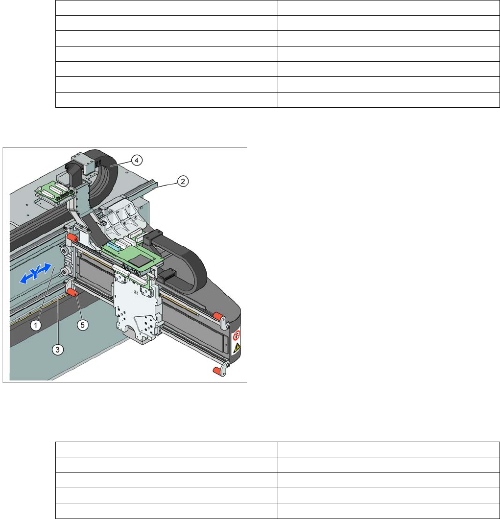
Y Axis Construction
Legend – main Y axis modules
1. Linear drive permanent magnet (secondary)
2. Linear guide rails
3. Linear incremental encoder
4. Trailing cable
5. Linear motor (primary)
The Y axis is driven by a linear motor. The secondary part
of the drive consists of a permanent magnet and is fixed
to the machine frame. The primary part is screwed to the
gantry arm.
Drive Direct, linear drive
Maximum speed 2.5 m/sec.
Gantry travel range 1430 mm
Length of incremental encoder 1850 mm
Resolution 1 µm
Overview
SIPLACE Vision Overview of Components
Student Guide SIPLACE X-Serie and X4I SW70x (AL2) 62
▪ Homogenous illumination of camera field of vision and components
Each C&P head has its own digital component camera. For Twin Heads, a stationary camera is installed
in the machine.
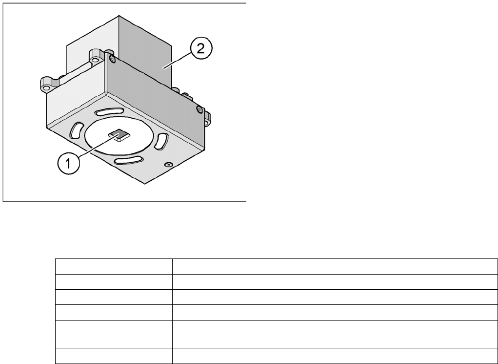
Digital PCB Camera (Standard) SST34
3.2.8.1 Digital PCB Camera (Standard) SST34
Technical Data
PCB camera under the gantry (X axis)
Legend
1. Camera lens system
2. Camera amplifier
Illumination control for blue and infrared LEDs in the
various illumination levels
PCB fiducials max. 3 per placement program
Field of vision 5.7mm x 5.7mm
Type of illumination Front lighting
Resolution 9.8µm/pixels
Fiducial size 0.3 to 2.5 mm (can be up to 3.0 mm, depending on the PCB conveyor
tolerance)
Camera type.sst 34.sst
Overview
Overview of Components SIPLACE Vision
63 Student Guide SIPLACE X-Serie and X4I SW70x (AL2)
Component Camera C&P20A
3.2.8.2 Component Camera C&P20A
Component Camera SST23
Component Camera SST23
Technical Data
Component Camera CPP
3.2.8.3 Component Camera CPP
Component Camera SST28
Component Camera SST28
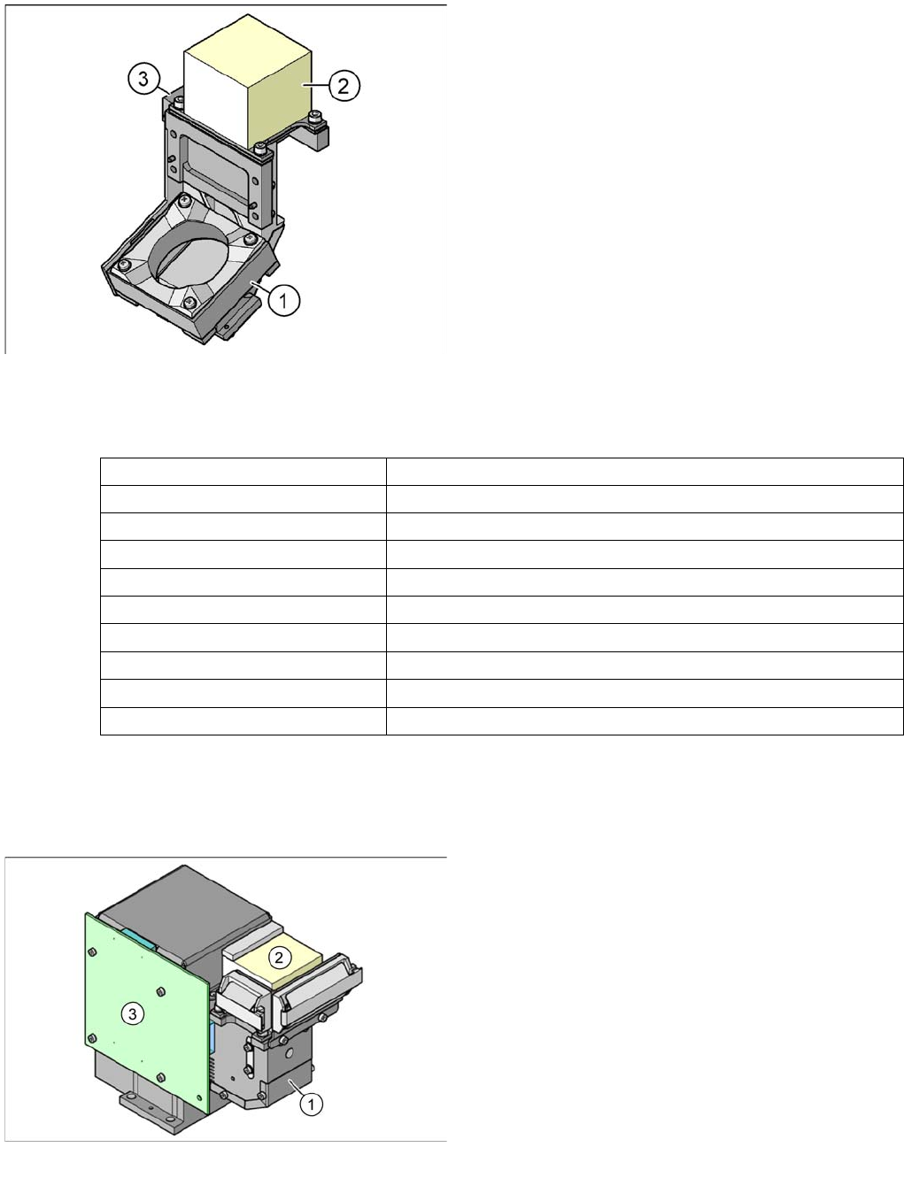
Component camera
Legend
1. Component camera lens system and illumination
2. Camera amplifier
3. Illumination controller
Component size 0.2 mm x 0.2 mm up to 6 mm x 6 mm
Components 01005 to 2220 (Flip CHIP, Bare Dies)
Minimum lead pitch 0.5 mm
Min. ball pitch 0.45 mm
Min. ball diameter 0.25 mm
Field of vision 8mm x 8mm
Type of illumination Front-lighting (5 levels, programmable as required)
Resolution 14.1 µm/pixels
Camera type.sst 23.sst
Application C&P20A (standard)
Component camera
Legend
1. Component camera lens system and illumination
2. Camera amplifier
3. Illumination controller