00194614-08 Trainingsdoku. SG X-Serie_X4i SW70x (AL2)_EN.pdf - 第65页
Overview Overview of Components SIPLACE Vision 65 Student Guide SIPLACE X-Serie and X4I SW70x (AL2) Note for SST29 Note for SST29 Component C amera SST38 Component Camera SST38 Technical Data Stationary Component Cameras…
Overview
SIPLACE Vision Overview of Components
Student Guide SIPLACE X-Serie and X4I SW70x (AL2) 64
Technical Data
Option: Digital camera (type 29.sst) for 0201 placement.
Component Camera SST29
Component Camera SST29
Technical data
Component size 0.5mm x 0.5 mm up to 18.7 mm x 18.7 mm
Component shape 0402 to PLCC44 incl. BGA, µBGA, flip-chip, TSOP, QFP,
PLCC, SO to SO32, DRAM
Minimum lead pitch 0.5 mm
Minimum ball pitch 0.45 mm
Minimum ball diameter 0.25 mm
Field of vision 24.5 mm x 24.5 mm
Type of illumination Front-lighting (4 levels, programable as required)
Resolution 50µm/Pixel
Camera type.sst 28.sst
Application C&P12 (standard), CPP (option)
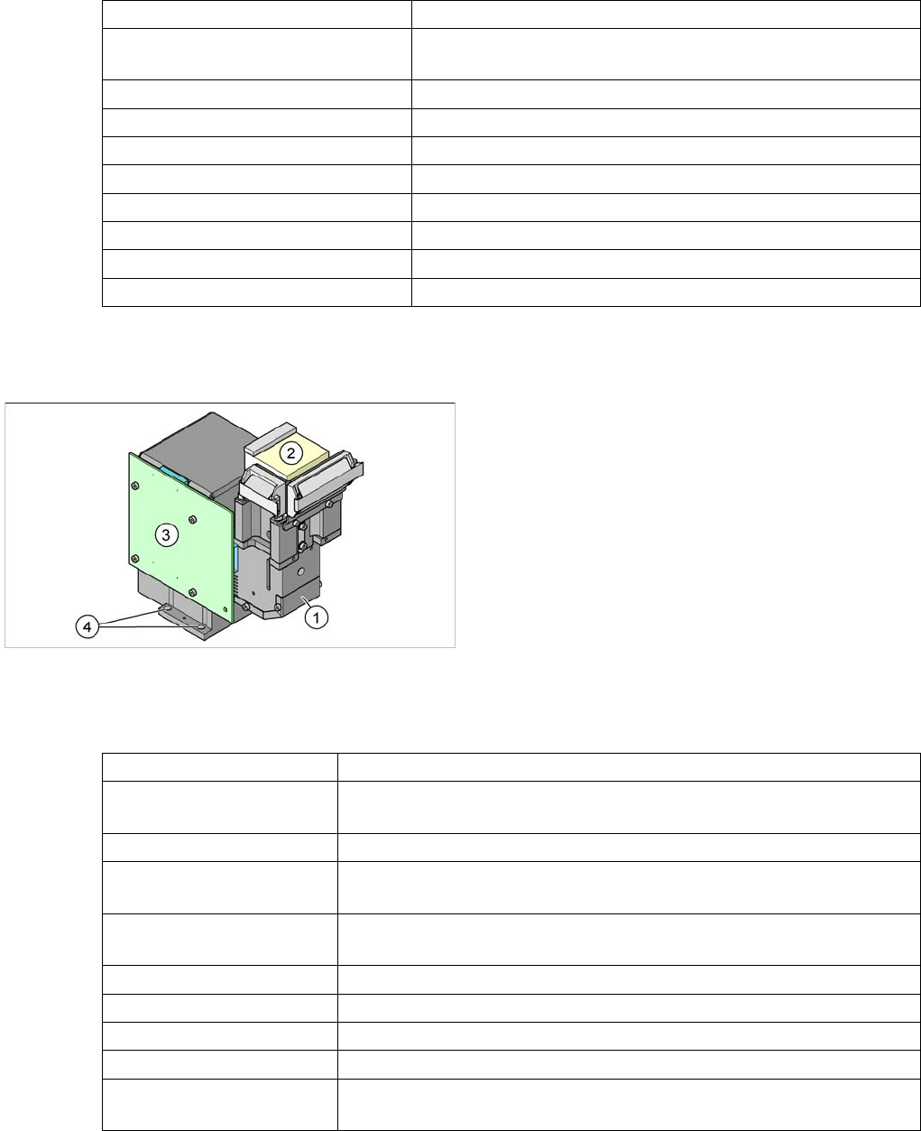
Component camera
Legend
1. Component camera optics and illumination
2. Camera amplifier
3. Illumination controller
4. Holes for fastening screws (4x)
Component size 0.3 mm x 0.3 mm to 27 mm x 27 mm
Components 0201 to 27 mm x 27 mm
PLCC, SO, QFP, TSDP, SOT, MELF, CHIP, ...
Minimum lead pitch 0.3 mm
Min. ball pitch 0.25 mm for CO < 18 x 18 mm
0.35 mm for CO >= 18 x 18 mm
Min. ball diameter 0.14 mm for CO < 18 x 18 mm
0.2 mm for CO >= 18 x 18 mm
Field of vision 32 mm x 32 mm
Illumination type Front illumination (4 levels individually programmable)
Resolution 26 µm/pixels
Camera type.sst 29.sst
Used with the following
heads
CPP (as default)
C&P6 (as default)
Overview
Overview of Components SIPLACE Vision
65 Student Guide SIPLACE X-Serie and X4I SW70x (AL2)
Note for SST29
Note for SST29
Component Camera SST38
Component Camera SST38
Technical Data
Stationary Component Cameras
3.2.8.4 Stationary Component Cameras
NOTICE
The component camera SST29 is the standard camera for the CPP head. The other cameras
can be ordered as an option.
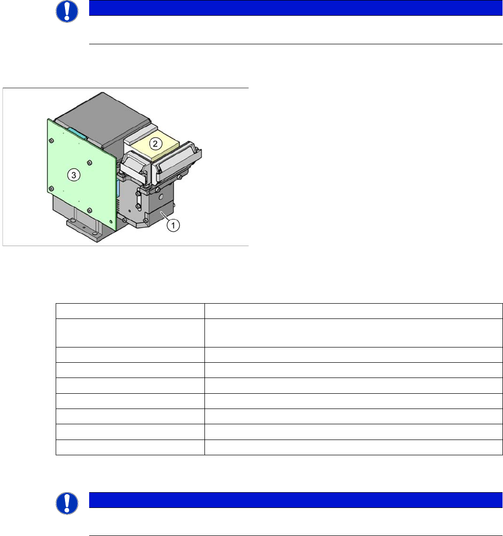
Component camera
Legend
1. Component camera lens system and illumination
2. Camera amplifier
3. Illumination controller
Component size 0.4x0.2 mm (01005) to 16x16 mm
Components 01005 to 16 mm x 16 mm
PLCC, SO, QFP, TSDP, SOT, MELF, CHIP, IC BGA
Min. ball pitch 250 µm
Min. ball diameter 140 µm
Field of vision 20 mm x 20 mm
Type of illumination Front-lighting (4 levels, programable as required)
Resolution 17 µm/pixels
Camera type.sst 38.sst
Application CPP (option)
NOTICE
The stationary cameras (IC, FC camera) version ≧ 04 from machine no. B160 also have a
Vision illumination control board for controlling the illumination levels.
Overview
SIPLACE Vision Overview of Components
Student Guide SIPLACE X-Serie and X4I SW70x (AL2) 66
Flip Chip Camera (Option) SST25
Flip Chip Camera (Option) SST25
Technical Data
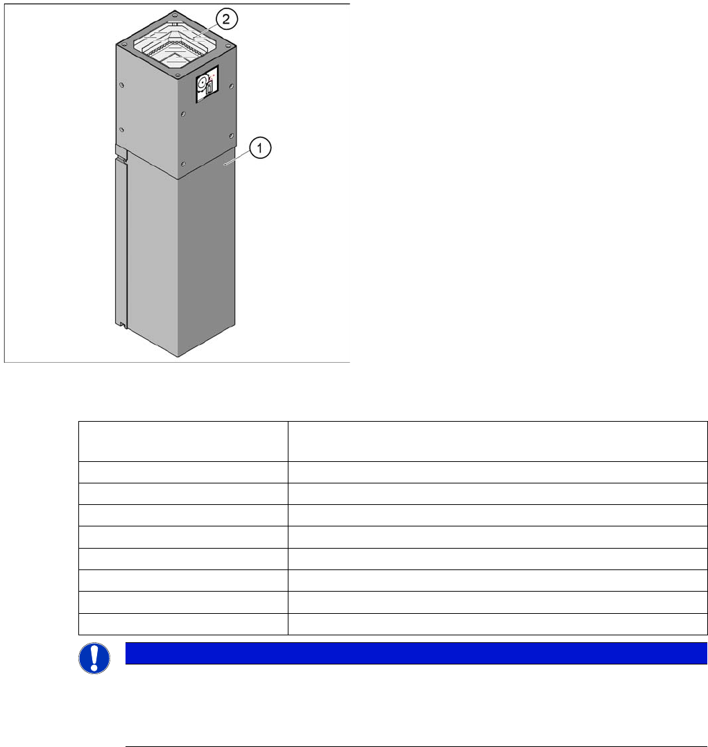
Legend
1. Camera housing with integrated camera and camera
amplifier
2. Inside: the 6 illumination and lens levels
The Flip Chip camera (FC camera) has a higher
resolution and therefore covers the remaining component
spectrum for the SMD components. The FC camera
construction is identical with that of the IC camera, with
its 6 illumination levels.
Component size 0.2 mm x 0.2 mm up to 16 mm x 16 mm for single measurement
mode
Components 01005, Flip Chip, µBGA, Bare Dies
Minimum lead pitch 0.25 mm
Min. ball pitch 0.14 mm
Min. ball diameter 0.08 mm
Field of vision 19 mm x 19 mm
Type of illumination Front-lighting (6 levels, programable as required)
Resolution 16µm/Pixel
Camera type.sst 25.sst
NOTICE
The stationary camera SST25 is fitted with a multiplexer from version 05 onwards. This enables
you to switch between two stationary cameras. However, the multiplexer is not used in the X
series.
► Note the cable connections!