00194614-08 Trainingsdoku. SG X-Serie_X4i SW70x (AL2)_EN.pdf - 第67页
Overview Overview of Components SIPLACE Vision 67 Student Guide SIPLACE X-Serie and X4I SW70x (AL2) IC Camera SST33 IC Camera SST33 Technical Data Legend 1. Came ra ho using with inte grated camera and camera amplifier 2…
Overview
SIPLACE Vision Overview of Components
Student Guide SIPLACE X-Serie and X4I SW70x (AL2) 66
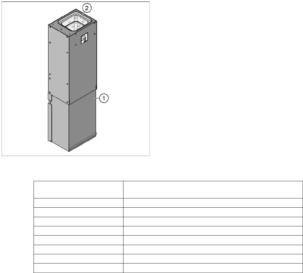
Flip Chip Camera (Option) SST25
Flip Chip Camera (Option) SST25
Technical Data
Legend
1. Camera housing with integrated camera and camera
amplifier
2. Inside: the 6 illumination and lens levels
The Flip Chip camera (FC camera) has a higher
resolution and therefore covers the remaining component
spectrum for the SMD components. The FC camera
construction is identical with that of the IC camera, with
its 6 illumination levels.
Component size 0.2 mm x 0.2 mm up to 16 mm x 16 mm for single measurement
mode
Components 01005, Flip Chip, µBGA, Bare Dies
Minimum lead pitch 0.25 mm
Min. ball pitch 0.14 mm
Min. ball diameter 0.08 mm
Field of vision 19 mm x 19 mm
Type of illumination Front-lighting (6 levels, programable as required)
Resolution 16µm/Pixel
Camera type.sst 25.sst
NOTICE
The stationary camera SST25 is fitted with a multiplexer from version 05 onwards. This enables
you to switch between two stationary cameras. However, the multiplexer is not used in the X
series.
► Note the cable connections!
Overview
Overview of Components SIPLACE Vision
67 Student Guide SIPLACE X-Serie and X4I SW70x (AL2)
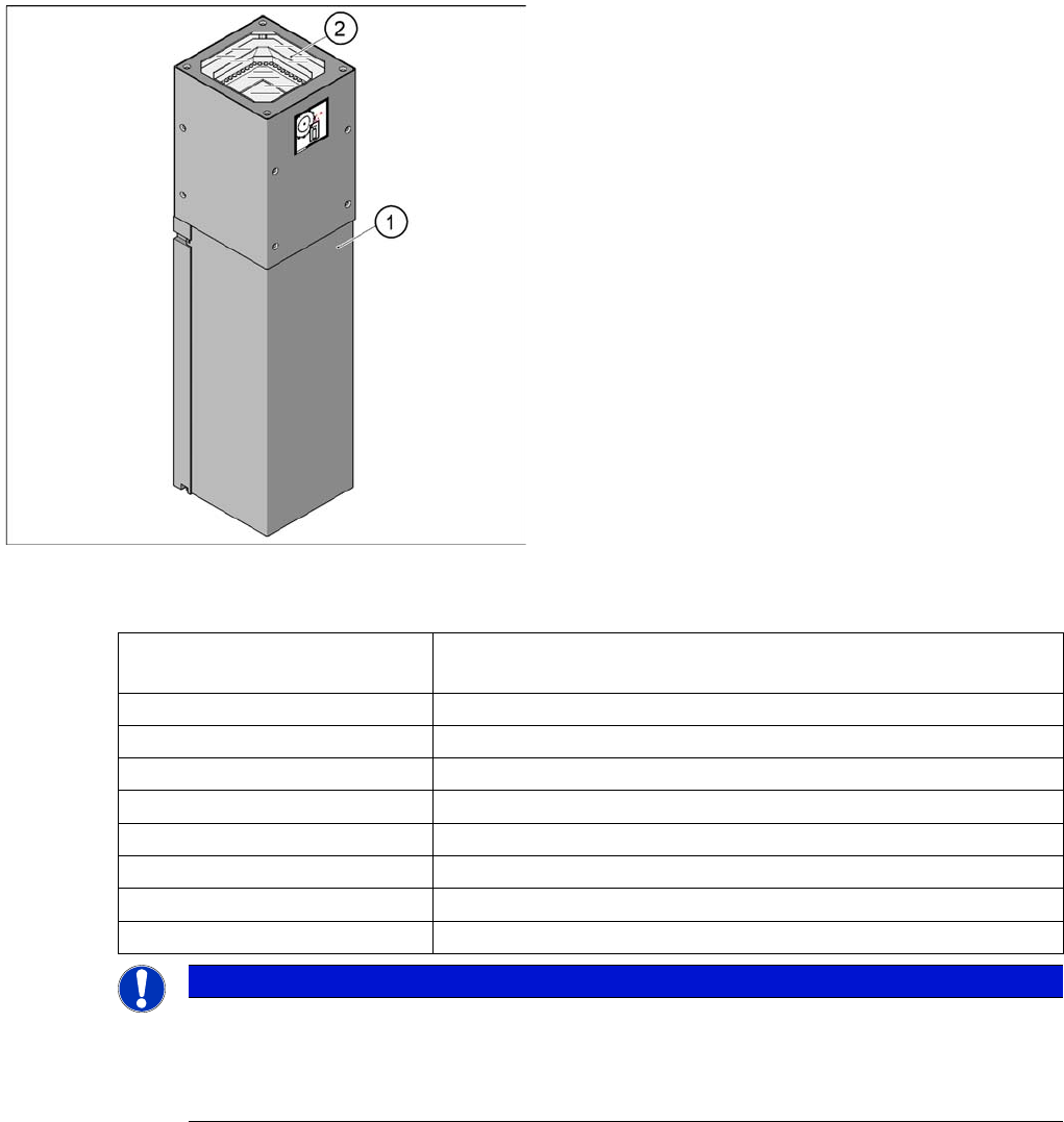
IC Camera SST33
IC Camera SST33
Technical Data
Legend
1. Camera housing with integrated camera and camera
amplifier
2. Inside: the 6 illumination and lens levels
Component size 0.5 mm x 0.5 mm up to 55 mm x 45 mm for single measurement
mode
Components 0402, MELF, SO, PLCC, QFP, electrolytic capacitors, BGA
Minimum lead pitch 0.3 mm
Min. ball pitch 0.45 mm
Min. ball diameter 0.25 mm
Field of vision 65 mm x 50 mm
Type of illumination Front-lighting (6 levels, programable as required)
Resolution 41µm/Pixel
Camera type.sst 33.sst
Overview
C&P20A Head Overview of Components
Student Guide SIPLACE X-Serie and X4I SW70x (AL2) 68
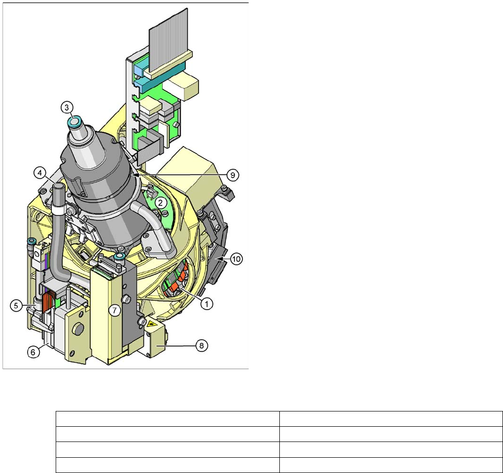
C&P20A Head
3.2.9 C&P20A Head
Technical Data
Description
3.2.9.1 Description
The C&P20A head works according to the Collect&Place principle (C&P), meaning that twenty
components are picked from the feeder modules (X feeders only) in one cycle. The component sensor
checks the pickup/place positions, to see whether a component has been taken by the nozzle or placed
on a board. On the way to the placement position, the components are rotated into the correct placement
position and optically centered. Before placement is performed, the angle and X/Y position correction,
determined by the Vision system, is applied. The X/Y position correction is calculated into the placement
position, while the angle correction is applied separately to each segment. This is possible as each
segment can be rotated independently of the star position. The components are then carefully and
accurately placed down on the board, with an air blast.
The component camera is still integrated into the C&P20A head. This saves additional travel to the
external centering cameras.
Legend
1. Star with 20 segments (DP drives)
2. Board for "hold circuit vacuum sensor"
3. Compressed air supply for holding, pickup and place
circuits
4. Cooling for X linear motor (discharged air from
pressure control valve)
5. Z axis return cylinder
6. Z linear motor with measuring system
7. Pressure control valve for pickup and place circuit
8. Component sensor
9. Star motor with incremental encoder
10. Component Camera
Components 01005 to 2220, Melf, SOT, SOD
Max. component size 6mm x 6mm x 4mm (LxWxH)
Min. component size 0.4 mm x 0.2 mm (01005)
Max. weight of component 1 g