00194614-08 Trainingsdoku. SG X-Serie_X4i SW70x (AL2)_EN.pdf - 第86页
Communication and Control Checking the Network Addresses Networking Address Student Guide SIPLACE X-Serie and X4I SW70x (AL2) 86 Vision Comp uter Box PC 4.2.1.2 Vision Computer Box PC Remote desktop connection The Vision…
Communication and Control
Networking Address Checking the Network Addresses
85 Student Guide SIPLACE X-Serie and X4I SW70x (AL2)
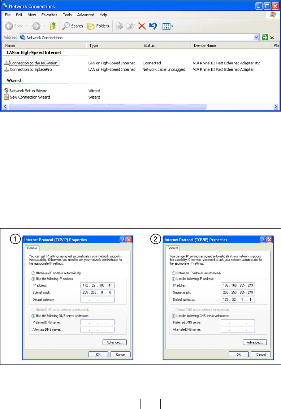
▪ Select TCP/IP and --> Select Properties (see below)
Network card 2 "connection to SIPLACE Pro":
The network connection between the station computer and SIPLACE Pro is realized via the LAN 2
connection of the dual LAN unit in the station computer. The network address is not fixed and can be
defined individually for each customer.
▪ Example of a LAN IP address: 172.22.208.181
This TCP/IP ADDRESS must be typed in, during the configuration of the station in SIPLACE Pro.
Network card 1 "connection to the MC Vision":
The internal network address for the station computer is a fixed local area network address, which must
not be changed.
▪ Station computer: 192.168.255.249
Network cards in the station computer
Legend
1 External IP address for SC 2 Internal IP address for SC
Communication and Control
Checking the Network Addresses Networking Address
Student Guide SIPLACE X-Serie and X4I SW70x (AL2) 86
Vision Computer Box PC
4.2.1.2 Vision Computer Box PC
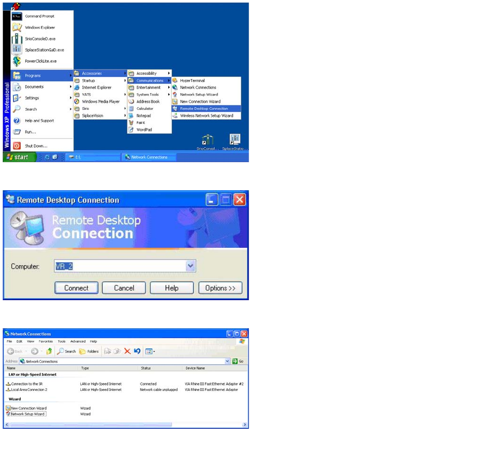
Remote desktop connection
The Vision computer has two network cards, which can
be directly set in Windows:
Access to the Vision computer is possible via a Remote
desktop connection .
► For this, select Start – Programs –
Accessories – Communications – Remote
Desktop Connection.
Remote desktop connection
► Enter the computer name VR_2 and select Connect.
You will now see the Windows XP basic view for the
Vision computer.
► Select Start --> Settings --> Network
connections.
Network connections
► Right-click with the mouse on the network card
Connection to the SR and select Select
Properties .
Communication and Control
CAN Bus Checking the Network Addresses
87 Student Guide SIPLACE X-Serie and X4I SW70x (AL2)
CAN Bus
4.3 CAN Bus
The development of CAN began when more and more electronic devices were implemented into modern
motor vehicles. All this means more safety and more comfort for the driver. Examples of such devices
include engine management systems, active control systems such as ABS, gear control, lighting control,
ventilation, air conditioning and central locking.
Communication via cable connection
To improve the behavior of the vehicle even further, it was necessary for the different control systems
(and their sensors) to exchange information. This was usually done by discrete interconnection of the
different systems (i.e. point to point wiring). The requirement for information exchange has then grown
to such an extent that a cable network with a length of up to several miles and many connectors was
required. This produced growing problems concerning material cost, production time and reliability.
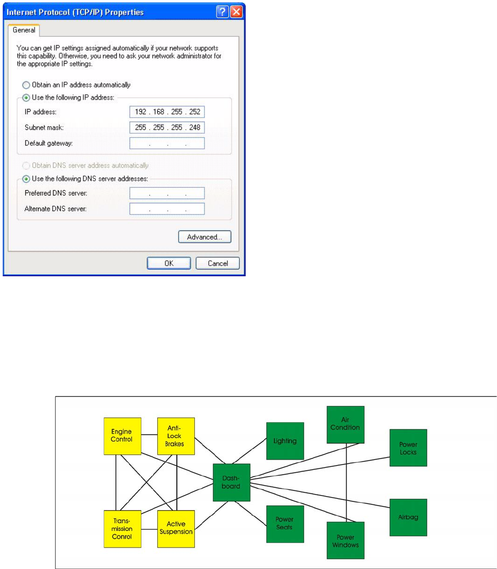
Internet protocol properties
► Select Internet Protocol (TCP/IP) from the
list and click on Select Properties.
▪ Network card 1: Connection to the SR:
The network connection between the Vision
computer and station computer is established via the
LAN 1 connection of both computers. The network
address is pre-fixed and may not be changed.
IP-Address Vision computer: 192.168.255.252
This TCP/IP address can only be checked or
changed by the system administrator.
▪ Network card 2: Local Area Connection 2:
This connection is not used.