00194614-08 Trainingsdoku. SG X-Serie_X4i SW70x (AL2)_EN.pdf - 第88页
Communication and Control General Structure CAN Bus Student Guide SIPLACE X-Serie and X4I SW70x (AL2) 88 The solution to th is problem was the connection of t he control systems via a serial bus system. This bus had to f…
Communication and Control
CAN Bus Checking the Network Addresses
87 Student Guide SIPLACE X-Serie and X4I SW70x (AL2)
CAN Bus
4.3 CAN Bus
The development of CAN began when more and more electronic devices were implemented into modern
motor vehicles. All this means more safety and more comfort for the driver. Examples of such devices
include engine management systems, active control systems such as ABS, gear control, lighting control,
ventilation, air conditioning and central locking.
Communication via cable connection
To improve the behavior of the vehicle even further, it was necessary for the different control systems
(and their sensors) to exchange information. This was usually done by discrete interconnection of the
different systems (i.e. point to point wiring). The requirement for information exchange has then grown
to such an extent that a cable network with a length of up to several miles and many connectors was
required. This produced growing problems concerning material cost, production time and reliability.
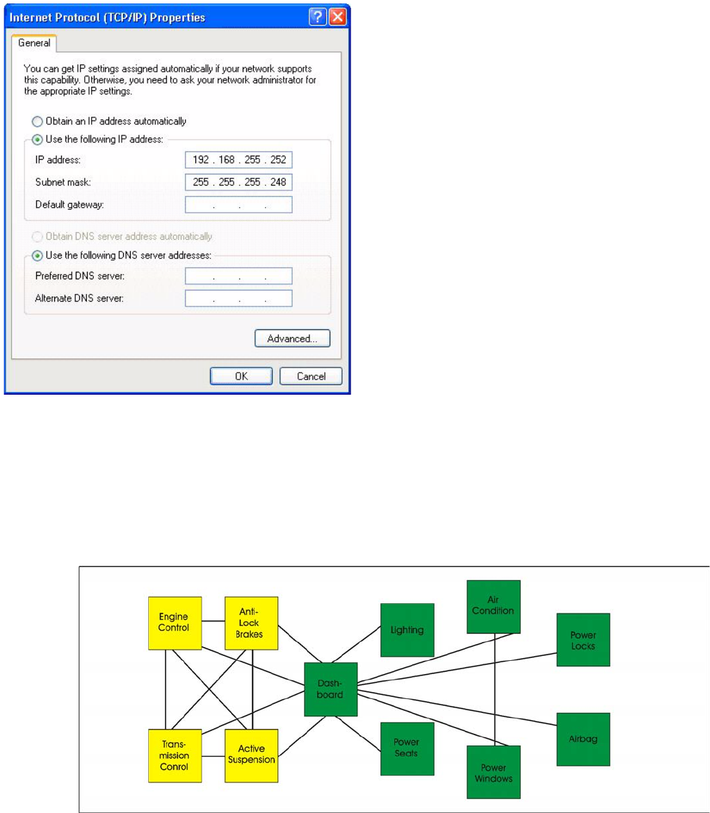
Internet protocol properties
► Select Internet Protocol (TCP/IP) from the
list and click on Select Properties.
▪ Network card 1: Connection to the SR:
The network connection between the Vision
computer and station computer is established via the
LAN 1 connection of both computers. The network
address is pre-fixed and may not be changed.
IP-Address Vision computer: 192.168.255.252
This TCP/IP address can only be checked or
changed by the system administrator.
▪ Network card 2: Local Area Connection 2:
This connection is not used.
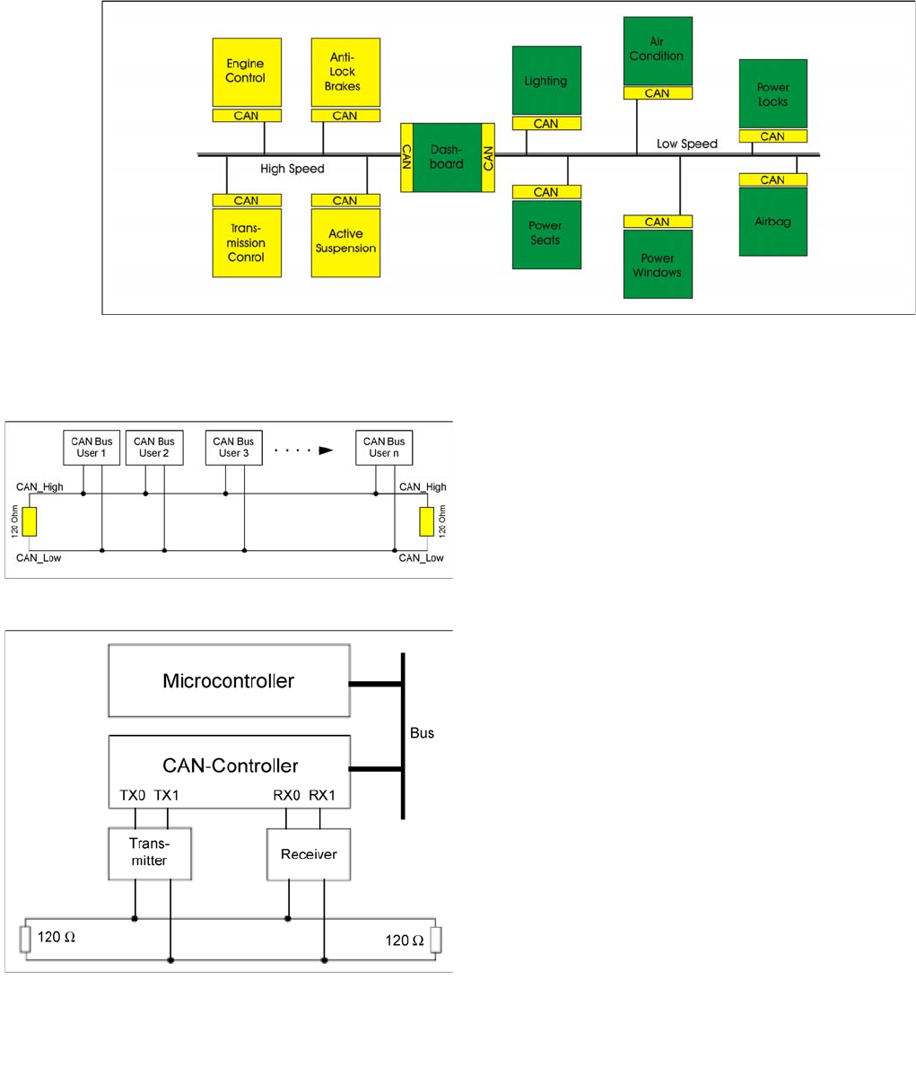
Communication and Control
General Structure CAN Bus
Student Guide SIPLACE X-Serie and X4I SW70x (AL2) 88
The solution to this problem was the connection of the control systems via a serial bus system. This bus
had to fulfill some special requirements due to its usage in a vehicle. With the use of CAN, point-to-point
wiring is replaced by one serial bus Each module is given a CAN Bus connection. This is accomplished
by adding some CAN-specific hardware to each control unit that provides the ’rules’ or protocol for
transmitting- and receiving information via the bus.
Communication via CAN bus
General Structure
4.3.1 General Structure
See also
4.3.2 CAN Bus Protocol [ ➙ 89]
CAN Bus
The CAN Bus is a decentral multi-master bus. The data
are transmitted via the differential voltage of the two
CAN_High and CAN_Low lines, which are each fitted with
a terminating resistance of 120 Ohm.
CAN Bus controller and microcontroller
Legend
▪ Microcontroller:
Exchanges data with the CAN controller
▪ CAN controller:
Adds the data frame, establishes the connection and
manages errors.
▪ Transmitter/receiver:
>Adjusts the level (driver levels)
Each bus node has a CAN controller, which can transmit
and receive data if the bus is free.
This CAN controller communicates with a
microcontroller. The microcontroller steers and controls
the relevant CAN bus nodes.
A CAN Bus node can only transmit if the bus is free i.e. if
there is no communication taking place with other nodes.
Access to the CAN BUS is fixed in the CAN protocol
(identifier). This results in differing priorities among the
individual CAN bus nodes.
Communication and Control
CAN Bus CAN Bus Protocol
89 Student Guide SIPLACE X-Serie and X4I SW70x (AL2)
4.3.2.2 CAN Bus Arbitration [ ➙ 89]
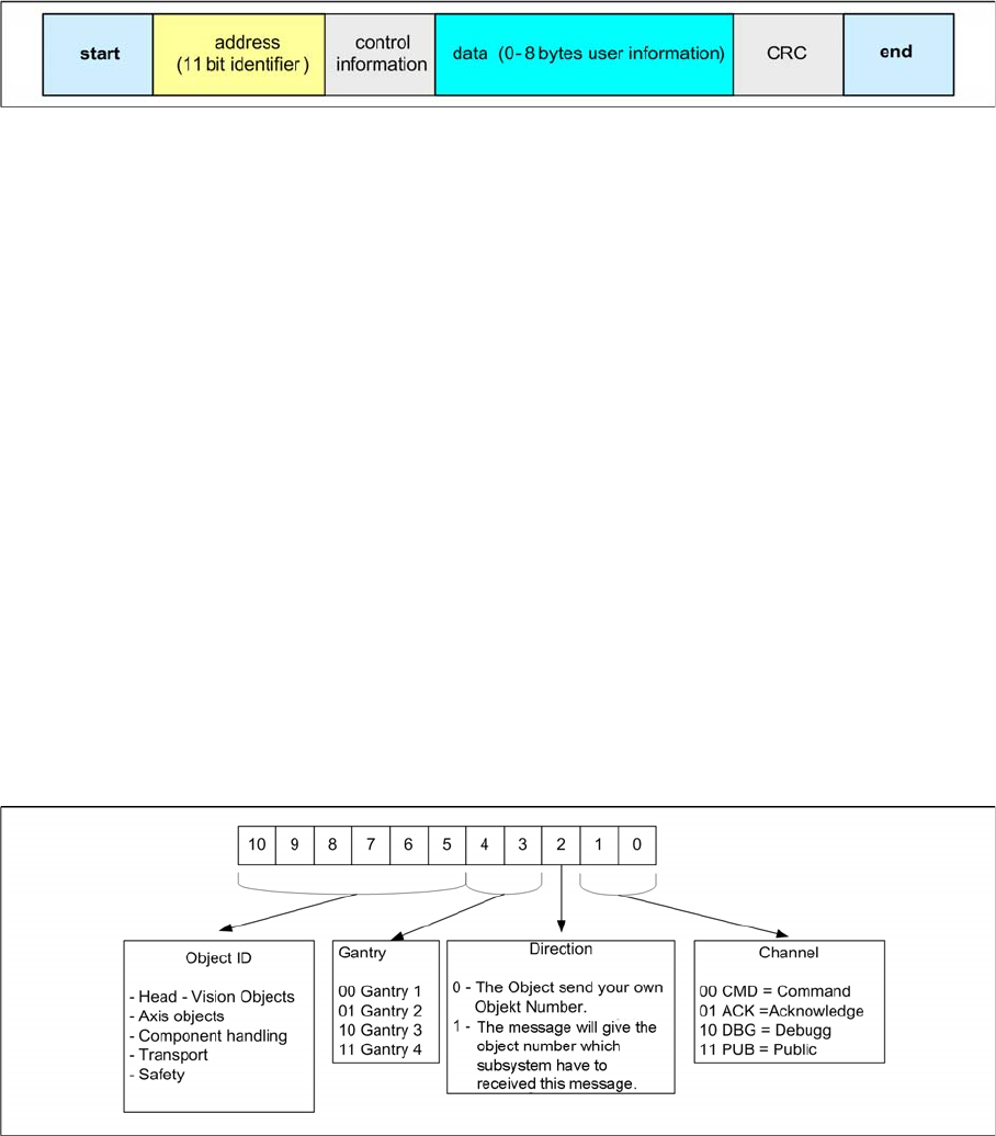
CAN Bus Protocol
4.3.2 CAN Bus Protocol
CAN Bus Protocol
▪ Start
This bit indicates the beginning of a telegram and is a dominant bit. After this bit is set, no other user
of the CAN bus is able to send.
▪ Address field (11 bit identifier)
The 11 bit address identifier value determines the bus access. The lower value has the highest
priority.
▪ Control field
The 4 lowest bits in the 6 bit field show the data length of the following data field in bytes (DLC: Data
Length Code.
▪ Data field
Contains the information actually required and can be from 0 byte to 8 byte. The transfer of a byte
begins with the most significant bit (the bit with the highest value).
▪ Data control field CRC
Consists of a 15 bit check sequence (CRC sequence + CRC delimiter = CRC Field - Cyclic
Redundancy Check) and a recessive delimiter bit. The redundant information in the control
sequence allows the receiver to check whether the message received has been falsified by
interference.
▪ End
Each data telegram is terminated by a sequence of 7 recessive bits.
11 Bit Iden tifier
4.3.2.1 11 Bit Identifier
11 Bit Identifier
The CAN bus system is using the 11 Bit identifier for addressing the different CAN objects
An 11 Bit identifier (address) identifies the type, priority, source and /or target of the message.
This identifier also controls the bus access (arbitration).
CAN Bus Arbitration
4.3.2.2 CAN Bus Arbitration
Arbitration (arbitration means decision)