IPS adjustment on the modules.pdf - 第41页
E dition 1 .0 IPS Adjustment for V arious H ead T ypes on the Module <H24G/H24 S/H24A > FK - 9F50 - 74 -0E 2-7 FUJI CORPORA TION 3. Use the bolt s below to adjust the ca mera po sition so t hat the center value, re…
Edition 1.0 IPS Adjustment for Various Head Types on the Module
<H24G/H24S/H24A>
FK-9F50-74-0E 2-6 FUJI CORPORATION
Adjusting t he Ca m e ra Installati on Posi t ion
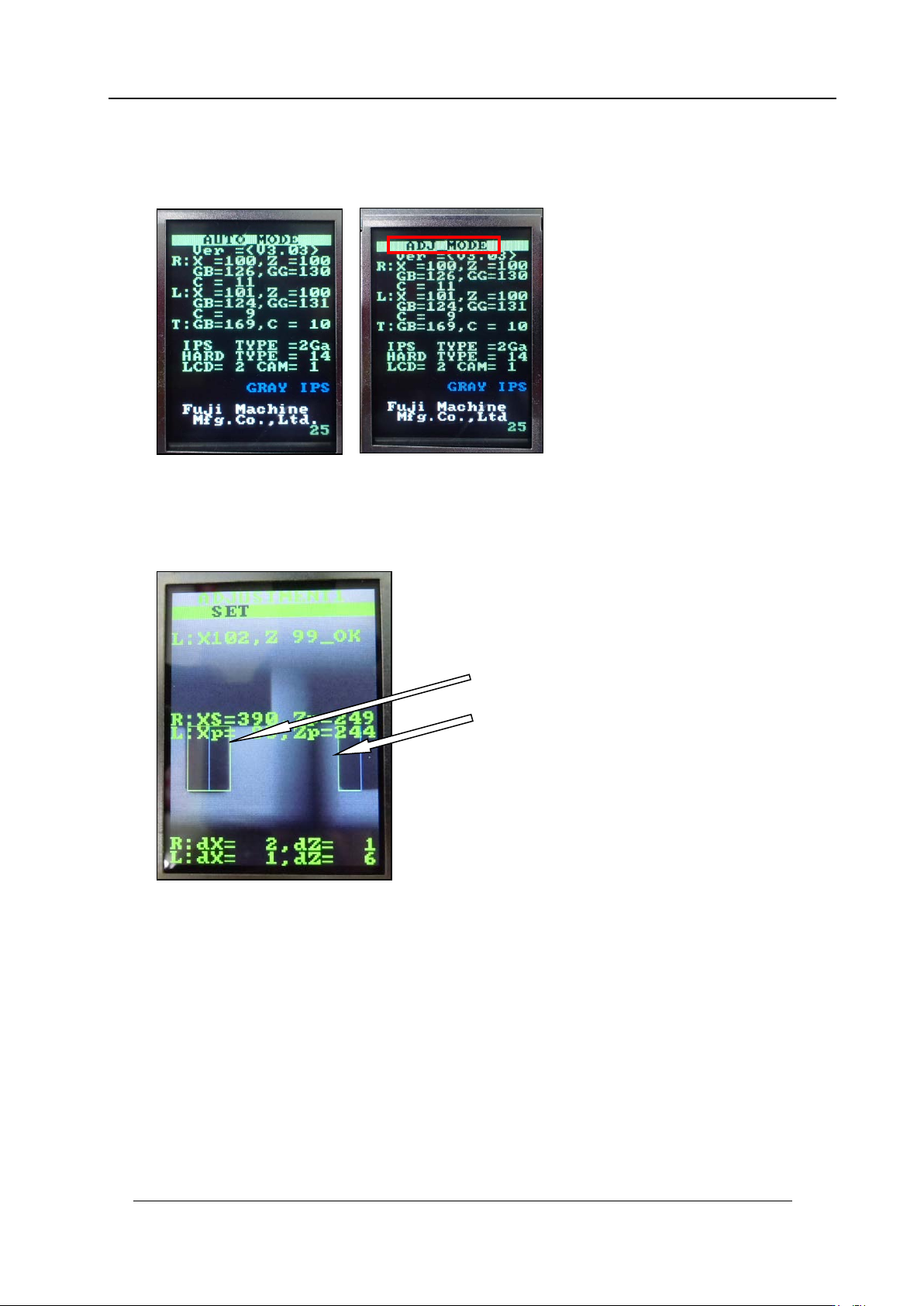
1. Press and ho ld t he lower button for a few seconds t o s hi f t to “ADJ MODE”.
2. Press the lower button to shift to “ADJUSTMENT 1” to flash the LED. Adjust the
position of the camera so that the jigs on the B and X holders match up with the green
frames on the s cr een.
The jigs match the
green frames on the
screen.
CONFIDENTIAL
Edition 1.0 IPS Adjustment for Various Head Types on the Module
<H24G/H24S/H24A>
FK-9F50-74-0E 2-7 FUJI CORPORATION
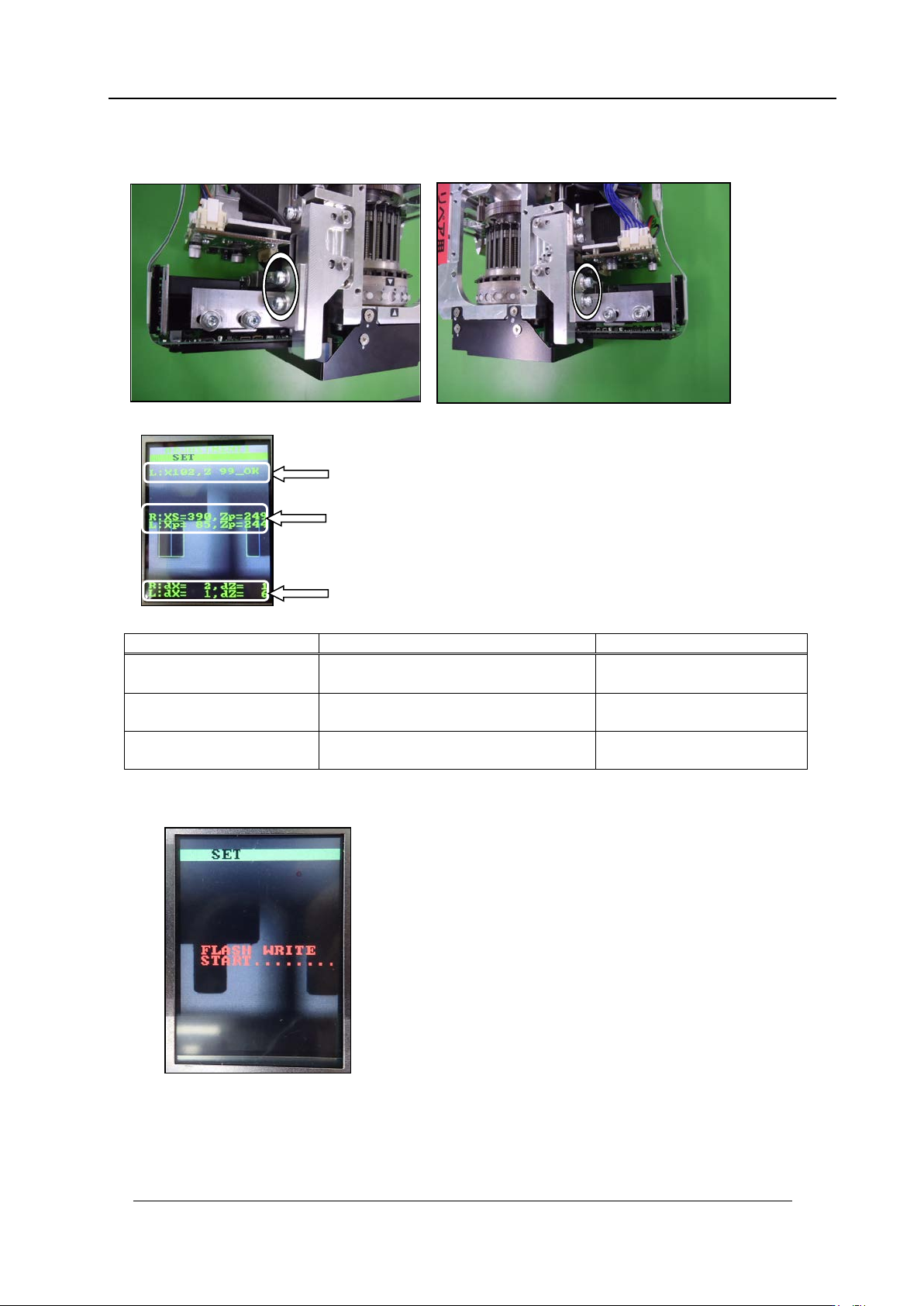
3. Use the bolts below to adjust the camera position so that the center value, resolution
and tilt are al l w ithin t olerance.
Inspection item
Tolerance
Target value
Camera resolution
L: X = 94~ 110
L: Z = 94~110
Same as tolerance
Center val ue
R: Xs = 380~4 00, Zp = 235~255
L: Xp = 80~ 100, Zp = 23 5~255
R: Xs = 390, Zp = 245
L: Xp = 90, Zp = 245
Tilt
R: dX = 0~6, dZ = 0~ 9
L: dX = 0~ 6, dZ = 0~ 9
R: dX = 0, dZ = 0
L: dX = 0, dZ = 0
4. If the results are w ithi n tolerance, pr ess the lower button t o save the sett ings.
5. Once savin g the setting s, r em ove the jig noz zles (2AGKNJ001500).
Resolution
Center val ue
Tilt
CONFIDENTIAL
Edition 1.0 IPS Adjustment for Various Head Types on the Module
<H24G/H24S/H24A>
FK-9F50-74-0E 2-8 FUJI CORPORATION
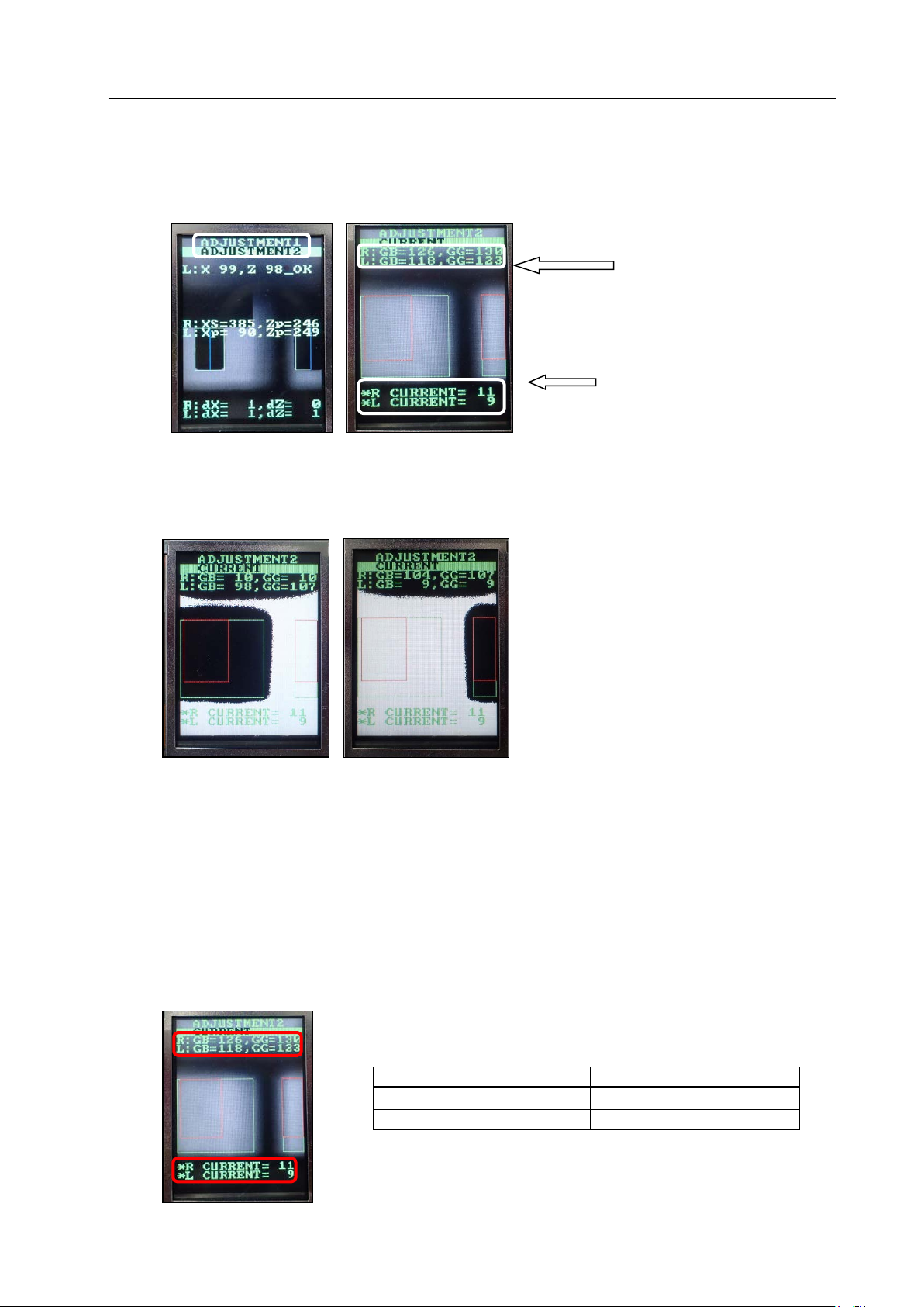
Adjusting the Current Value (Gr ayscale Value): Adjustment 2
1. Press the upper button to change to [ADJUSTMENT 2] mode from [Adjustment 1].
Press the low er but t on t o display t he c ur rent values .
2. Press the upper and lower buttons s i m ultaneously t o rev er se the LCD contrast ,
Block the right-hand glass and check there is no effect on the left-hand area. Block the
left-hand glass and check there is no effect on the right-hand area. Attach the dia m et er
0.2 mm noz zle and check that the image is complet ely white.
3. Press the upper and lower buttons simultaneously to set the LCD contrast back to
normal.
4. Rotate the R-axis through one full rotation and confirm that there is no position where
the variation in the grayscale values (R:GB and L:GB) is extreme. If the grayscale
value is too big, check the fluorescent status. If it is dirty, clean or replace it as
necessary.
5. Rotate the R-axis by hand to find the positions where the grayscale values (R:GB and
L : GB) are maximized and minimized. Check that the minimum and maximum
grayscale v alues are within the tolerance of 140~160 (target: 150).
6. Also check that the current v alue is 24 m A or less.
Tolerance
Target
R
:
GB , L
:
GB (Gray value)
140~160
150
CURRENT
24mA or less
Grayscale
values
Current
values
CONFIDENTIAL