IPS adjustment on the modules.pdf - 第116页
Edition 1 .0 IPS Adjustment for V arious Head T ypes on the Module <H08MQ head > FK - 9F50 - 74 -0 E 6-2 FUJI CORPORA TION Prep aratio n 1. Remov e t he cov ers. 2. Attach the jigs ( AA9F A0* ) to holders B and H o…
Edition 1.0
IPS Adjustment for Various Head Types on the Module
<H08MQ head>
FK-9F50-74-0E
6-1
FUJI CORPORATION
Chapter 6 – H08MQ head IPS Adjustment
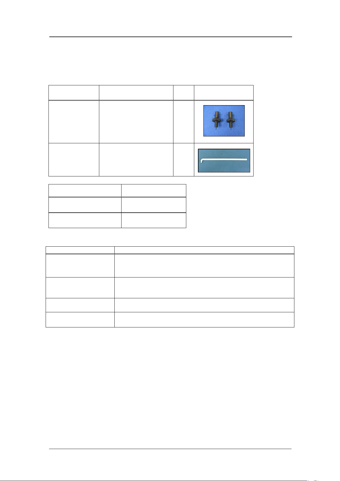
Requir e d jigs
Drawing No. Name QTY Photo
AA9FA0*
parts side recognition
camera resolut ion jig
2
2MGKHJ003600
Wrench (non-conducting
type)
1
Name
Note
Motion Too l Mini
For NXT2 series
Motion Adjustment To o l
For NXT3 series
Inspection item
Tolerance
LED current adjustm ent
Adjust the current value s o that the GR and GL gray values
are within the range 95 to 250. The target value is 100 +/-
5. Current = 26 mA or below.
Camera resolution
check
L: X = 90 ~ 100
L: Z = 90 ~ 100
Center val ue
R: Xs = 390 ± 20
Zp = 320 ± 20
L: Xp = 90 ± 25
Zp = 320 ±10
Tilt
R: dX = 0~9 (Target: 0), dZ = 0~9 (Target: 0)
L: dX = 0~9 (Target: 0
)
, dZ = 0~9 (Target: 0)
CONFIDENTIAL
Edition 1.0
IPS Adjustment for Various Head Types on the Module
<H08MQ head>
FK-9F50-74-0E
6-2
FUJI CORPORATION
Preparation
1. Remov e t he covers.
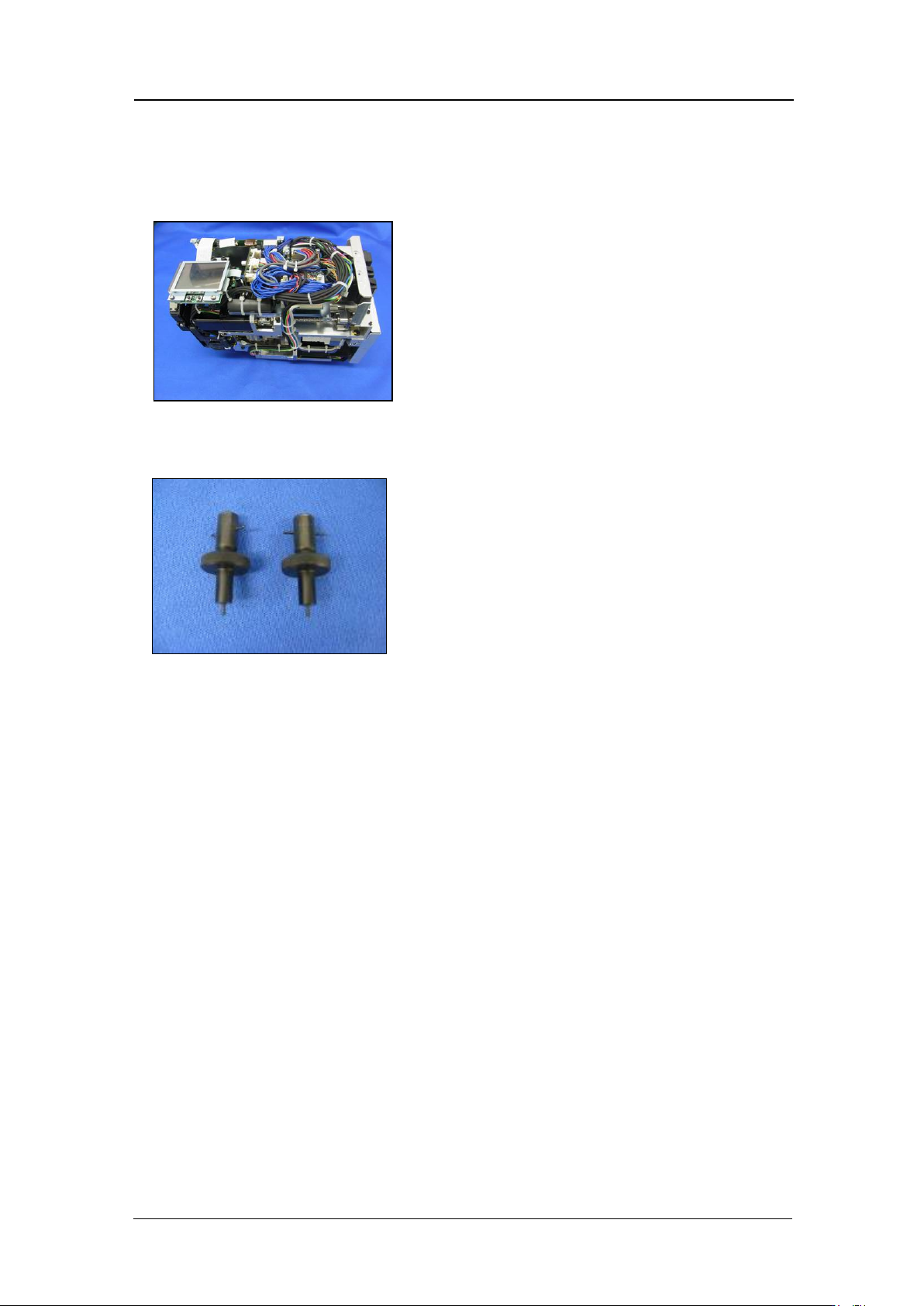
2. Attach the jigs (AA9FA0*) to holders B and H on the head, and then attach the head to
the module.
3. Attach the head to t he module and t ur n t he base pow er O N.
4. To adjust the IPS camera position, it is necessary to move the R-axis to the A-holder
proper data pos ition.
5. Use the Mot ion Tool M ini s oftw are to check the s er vo count o f the head on the module.
6. Push the START button at the main screen to rotate the R-axis. Check that holder A
has moved t o t he front of the hea d and t hen press the CYCLE STOP butt on.
7. Startup Mot ion Tool Mini.
CONFIDENTIAL
Edition 1.0
IPS Adjustment for Various Head Types on the Module
<H08MQ head>
FK-9F50-74-0E
6-3
FUJI CORPORATION
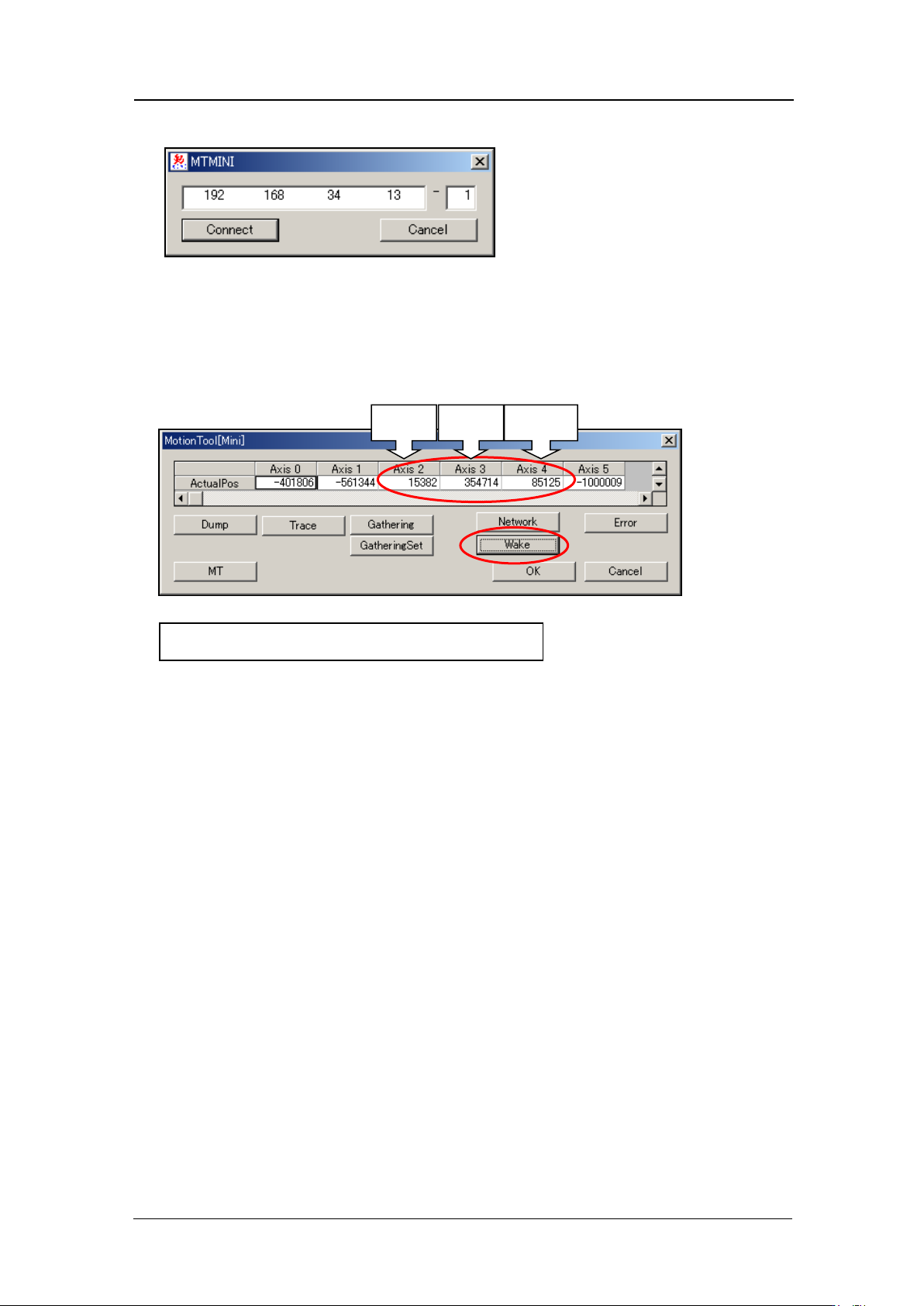
8. Enter the bas e I P address and the mod ule number, and then click [Connect].
9. Select [Wake] - [Automatic recognition] – [OK] to turn the servo power ON. After
approximately 10 seconds, the current servo count for each of the axes dis plays. Axi s 3
is the R-axis servo counter. Record this value. When adjusting the camera, the
adjust ment is performed with the R-axis at this position (the position where the A-holder
is at the front o f the head).
Z-axis
R-axis
Q-axis
Axis 3 : Reference value 30000
±
3000 pulses
CONFIDENTIAL