IPS adjustment on the modules.pdf - 第118页
Edition 1 .0 IPS Adjustment for V arious Head T ypes on the Module <H08MQ head > FK - 9F50 - 74 -0 E 6-4 FUJI CORPORA TION The foll owing ste ps ex plain how t o check the s er v o counter us ing Motion Adjust ment…
Edition 1.0
IPS Adjustment for Various Head Types on the Module
<H08MQ head>
FK-9F50-74-0E
6-3
FUJI CORPORATION
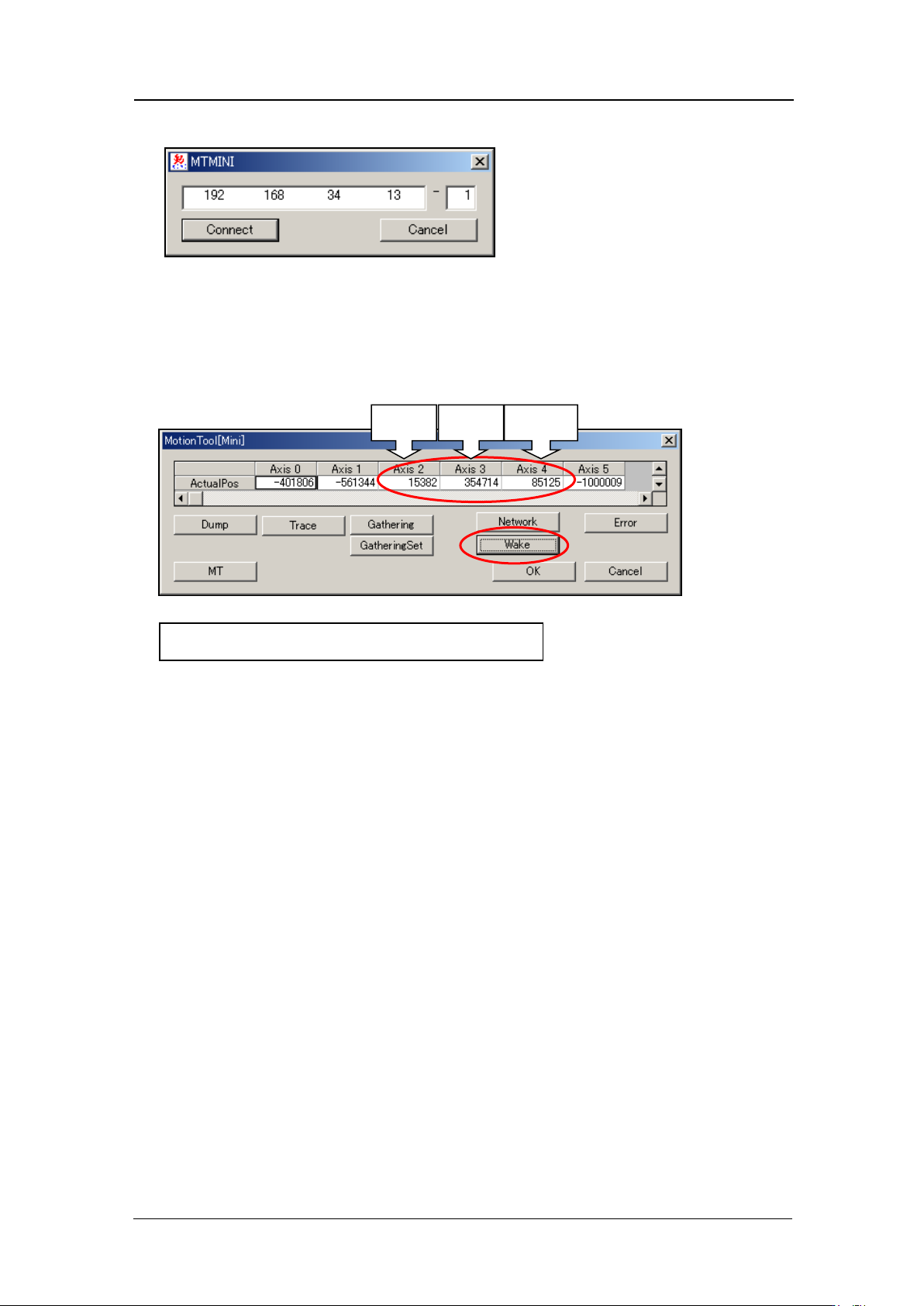
8. Enter the bas e I P address and the mod ule number, and then click [Connect].
9. Select [Wake] - [Automatic recognition] – [OK] to turn the servo power ON. After
approximately 10 seconds, the current servo count for each of the axes dis plays. Axi s 3
is the R-axis servo counter. Record this value. When adjusting the camera, the
adjust ment is performed with the R-axis at this position (the position where the A-holder
is at the front o f the head).
Z-axis
R-axis
Q-axis
Axis 3 : Reference value 30000
±
3000 pulses
CONFIDENTIAL
Edition 1.0
IPS Adjustment for Various Head Types on the Module
<H08MQ head>
FK-9F50-74-0E
6-4
FUJI CORPORATION
The following steps explain how to check the s er vo counter using Motion Adjustment Tool.
10. After the machine wakes up, press [Start] button and then press [Cycle stop] button
immediately.
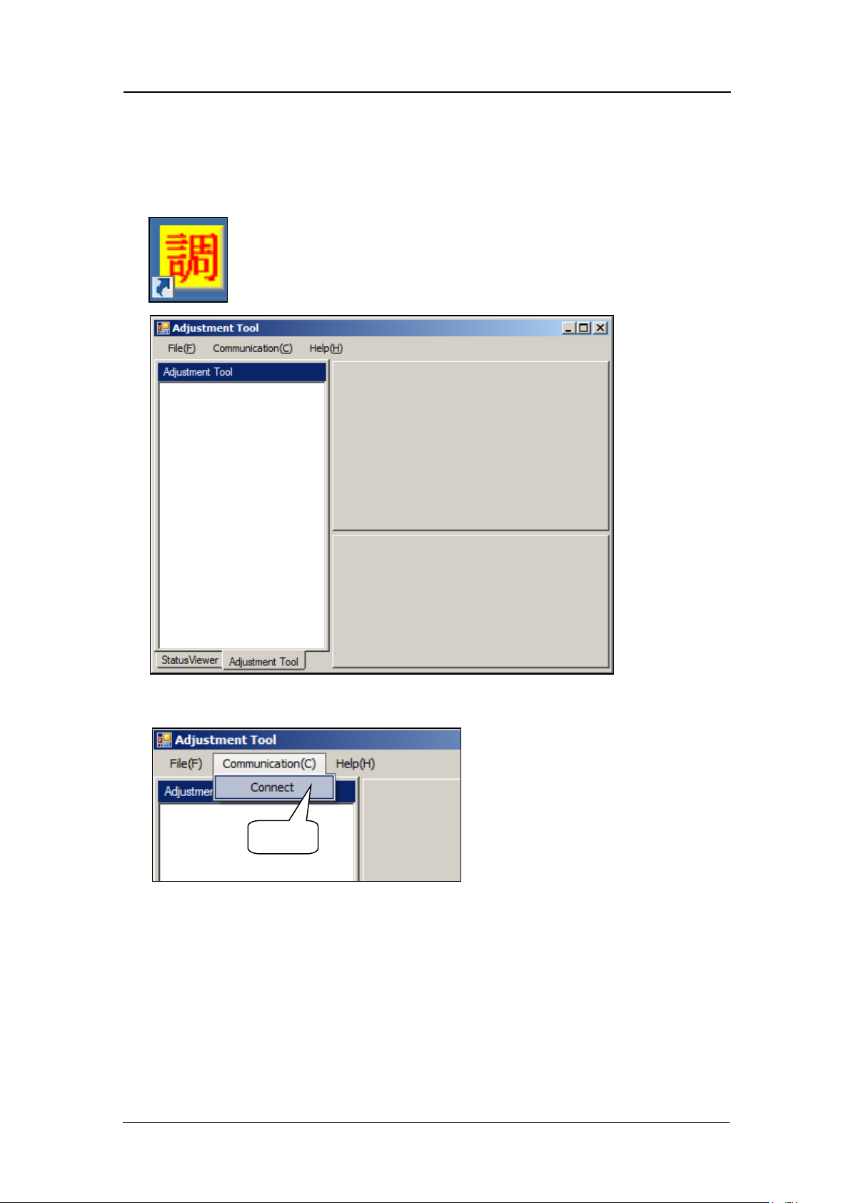
11. St ar t up M otion Adjust m ent Tool.
12. Select [Communication] – [Connect].
Select
CONFIDENTIAL
Edition 1.0
IPS Adjustment for Various Head Types on the Module
<H08MQ head>
FK-9F50-74-0E
6-5
FUJI CORPORATION
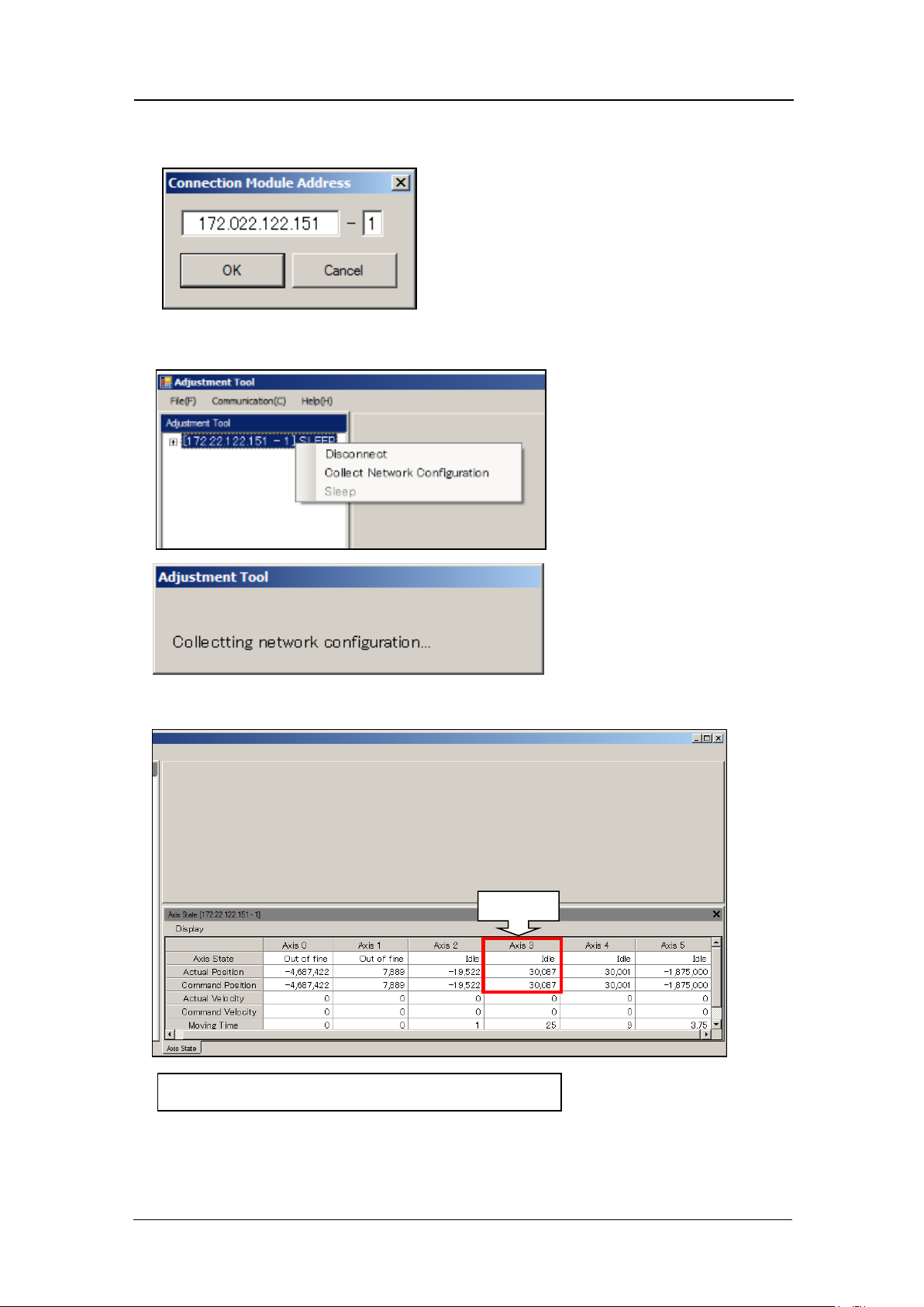
13. Enter the IP address of the target base and the module number, and then select
[Connect].
14. Right-click on the IP address and then se lect [ Collect Network Con fig ur at i on].
15. Record the Axis 3 ( R-axis serv o count er ) value.
Axis 3 : Reference v alu e 30000
±
3000 pulses
R-axis
CONFIDENTIAL