IPS adjustment on the modules.pdf - 第125页
Edition 1 .0 IPS Adjustment for V arious Head T ypes on the Module <H08MQ head > FK - 9F50 - 74 -0 E 6- 11 FUJI CORPORA TION 7. Press the low er but t on t o save t he s et t ings . 8. Remov e t he jigs In spection…
Edition 1.0
IPS Adjustment for Various Head Types on the Module
<H08MQ head>
FK-9F50-74-0E
6-10
FUJI CORPORATION
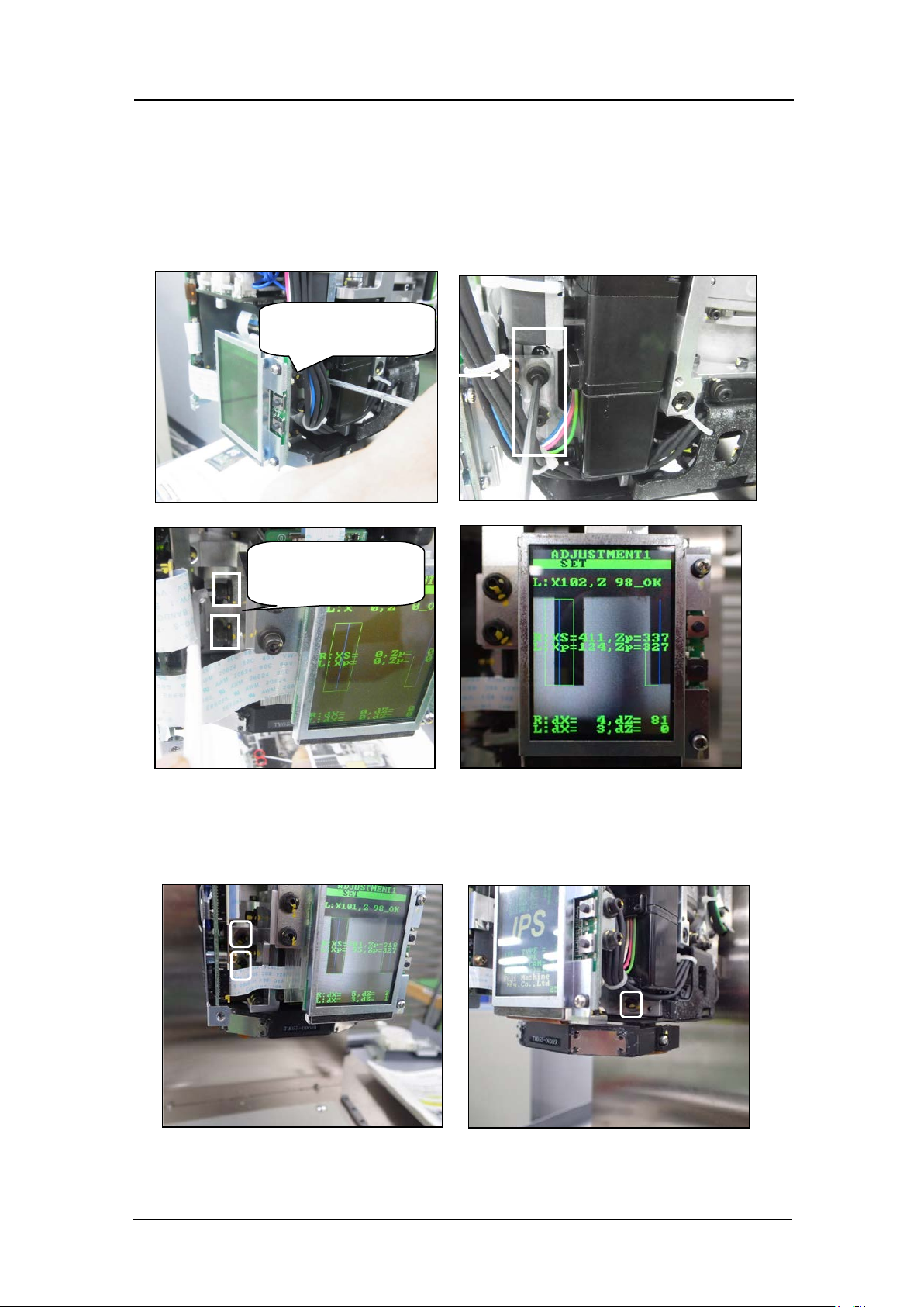
4. Adjust the position o f the camera so th at t he jig s on the B and H hol ders match up w ith
the green frames on t he screen.
5. Loosen the bolts on t he left and r i ght , and move t he camera b ack and forth to adjust
the pitch o f jig nozzles.
If the monit or i m age free zes during t he adjustme nt, it is necessary to return
to ADJUSTM ENT 1 and enter ADJUSTMENT 1 again.
6. Loosen the 3 bolts and move the camera in the XY direction so the nozzles
align with the green frames on the LCD monitor. Then check that the center
values, res ol ution and tilt are within tolerance.
Left a s vie wed f rom
front
Right as viewed
from front
CONFIDENTIAL
Edition 1.0
IPS Adjustment for Various Head Types on the Module
<H08MQ head>
FK-9F50-74-0E
6-11
FUJI CORPORATION
7. Press the low er but t on t o save t he s et t ings.
8. Remov e t he jigs
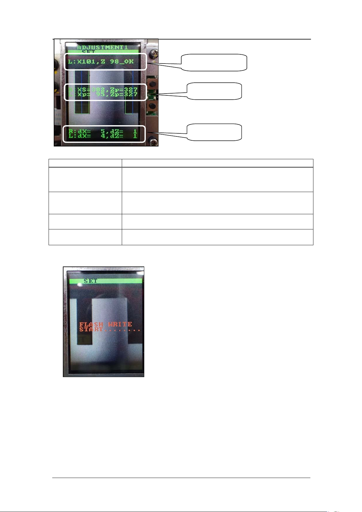
Inspection item
Tolerance
LED current adjustm ent
Adjust the current value s o that the GR and GL gray values
are within the range 95 to 250. The target value is 100 +/-
5. Current = 26 mA or below.
Camera resolution
check
L: X = 90 ~ 100
L: Z = 90 ~ 100
Center val ue
R: Xs = 390 ± 20
Zp = 320 ± 20
L: Xp = 90 ± 25
Zp = 320 ±10
Tilt
R: dX = 0~9 (Target: 0), dZ = 0~9 (Target: 0)
L: dX = 0~9 (Target: 0
)
, dZ = 0~9 (Target: 0)
Resolution values
Center val ues
Tilt v alues
CONFIDENTIAL
Edition 1.0
IPS Adjustment for Various Head Types on the Module
<H08MQ head>
FK-9F50-74-0E
6-12
FUJI CORPORATION
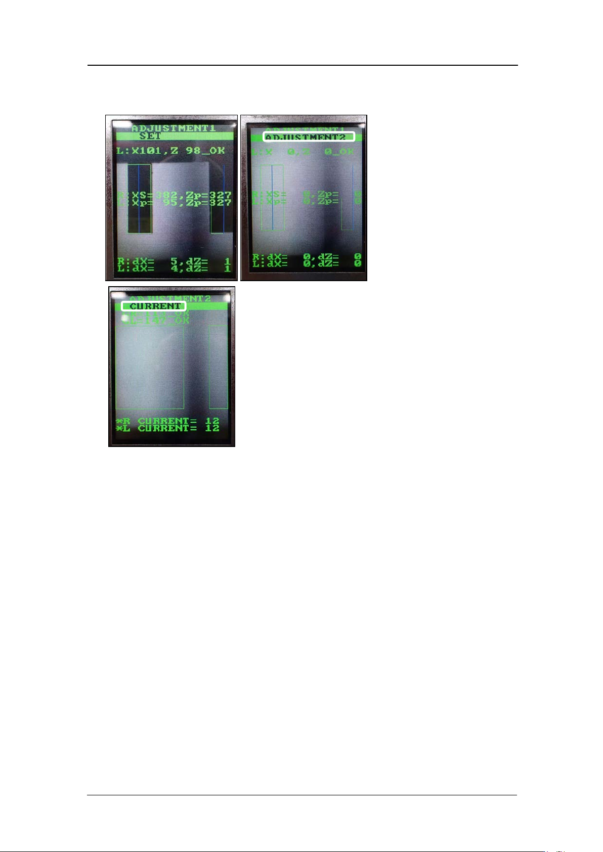
Adjusting the current value (grayscale value)
1. Press the low er but t on t o display t he cur r ent and grayscale valu es.
2. Rotate the R-axis by hand to find the positions where the grayscale values (GR and
GL) are maximized and minimized. Check that the minimum and maximum grayscale
values are within the to lerance show n below.
R: 90~170 Target: 100
L: 110~130 Target: 100
3. Also check that the current value is 26 mA or less, and the edge of a 0.3 mm nozzle
can be seen c learly.
4. Rotate the R-axis through one full rotation and confirm that there is no position where
the variation in the grayscale values (GR and GL) is extreme. Pay particular attention
to the variation in grayscale values at the position where the fluorescent sticker is
joined. If the variat ion i s la r ge, c lea n t he fluoresce nt sticker and r eplace it if necessary.
CONFIDENTIAL