IPS adjustment on the modules.pdf - 第135页
Edition 1.0 IPS Adjustment for V ari ous Head T yp es on the Module < G04Q h ead > FK - 9F50 - 74 -0 E 7- 1 FUJI CORPORA T IO N Chapter 7- G04 Q head I PS a djustme nt Camer a positi on adjustment , current val ue …

CONFIDENTIAL
Edition 1.0 IPS Adjustment for Various Head Types on the Module
<G04Q head>
FK-9F50-74-0E 7- 1 FUJI CORPORATION
Chapter 7- G04Q head IPS adjustment
Camera position adjustment, current value (grayscale value)
adjustment, and area check
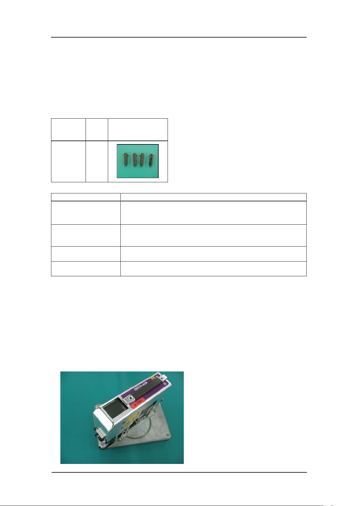
Required jigs
Drawing
No.
Qty
Photo
AA6MG0*
4
Tolerance
Inspection item
Tolerance
LED current
adjustment
Adjust the current value so that the grayscale value is 120 or
above.
CURRENT
=
20 mA or l ess
Camera resolution
check
A, B, C, D = 90 ~ 110
Camera position
check
MA = [420 +/- 15, 320 +/- 25], MB = [60 +/- 15, 320 +/- 25],
MC = [180 +/- 15, 320 +/- 25], MD = [300 +/- 15, 320 +/- 25]
Tilt
R: dX = 0~9 (tar get value: 0), dZ = 0~9 (target value: 0)
L: dX = 0~9 (target value: 0), dZ = 0~9 (tar get value: 0)
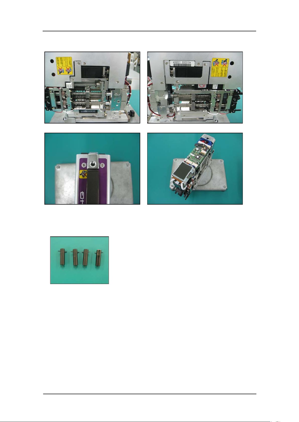
Removing the head co ver
1. Remove the cover
Caution: The rotary holder lower bracket may become bent if the head is laid down
to remove the cover.
Therefore, the head should be kept in an upright
positi on whe n r e m ovin g the cover.
Note: Usin g a head maintenance stand is r ecommended.
CONFIDENTIAL
Edition 1.0 IPS Adjustment for Various Head Types on the Module
<G04Q head>
FK-9F50-74-0E 7- 2 FUJI CORPORATION
2. Remove the si de bolts.
Preparation at the module
1. Attach the jigs
2. Attach the h ead t o the modul e.
3. Tur n t he base main switch ON.
4. This complete s t he pr eparation for the ca m er a position ad justment.
CONFIDENTIAL