IPS adjustment on the modules.pdf - 第136页
Edition 1.0 IPS Adjustment for V ari ous Head T yp es on the Module < G04Q h ead > FK - 9F50 - 74 -0 E 7- 2 FUJI CORPORA T IO N 2. Remove the si de b olts. Preparation at the module 1. Attach the jig s 2. Attach th…
Edition 1.0 IPS Adjustment for Various Head Types on the Module
<G04Q head>
FK-9F50-74-0E 7- 1 FUJI CORPORATION
Chapter 7- G04Q head IPS adjustment
Camera position adjustment, current value (grayscale value)
adjustment, and area check
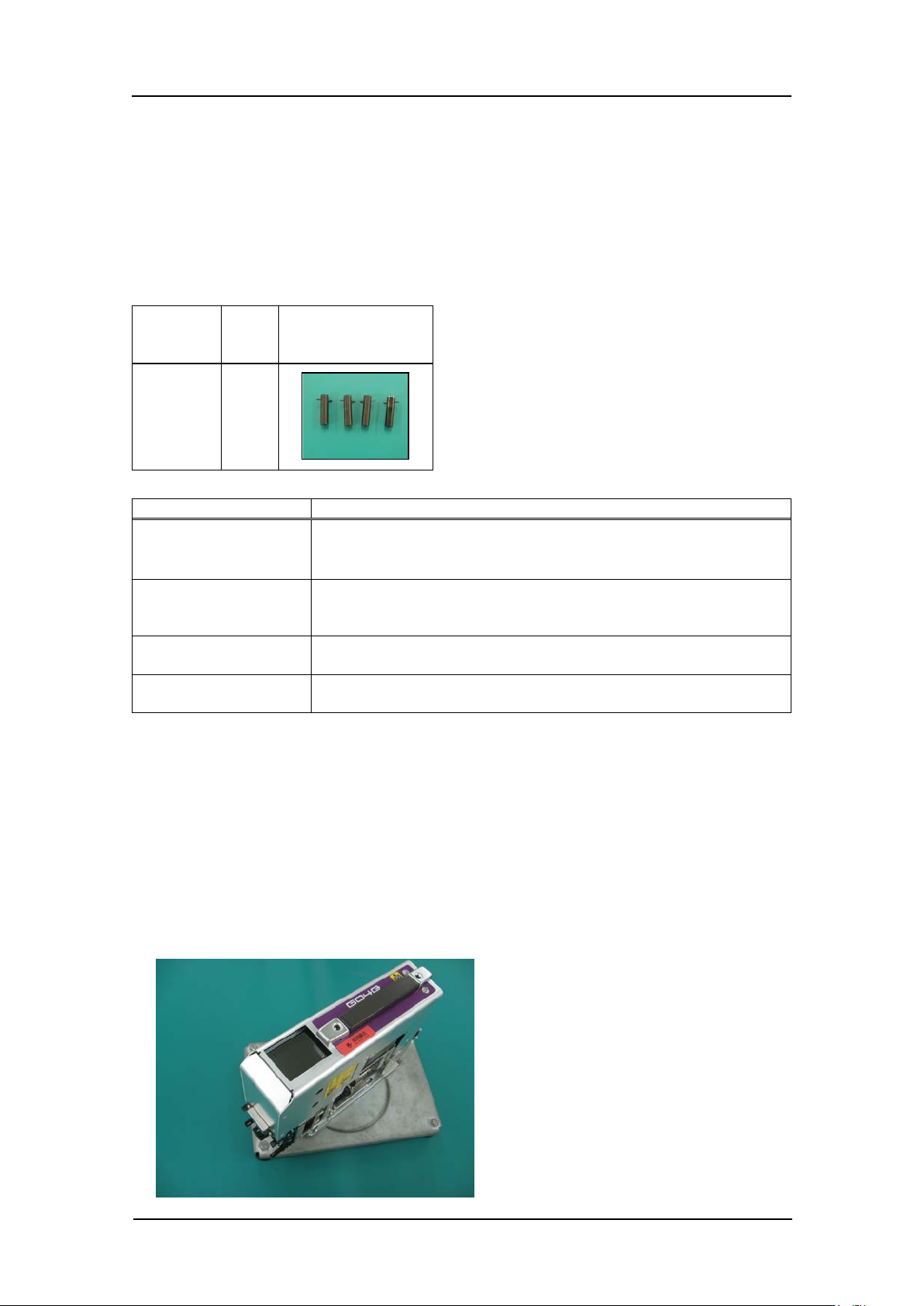
Required jigs
Drawing
No.
Qty
Photo
AA6MG0*
4
Tolerance
Inspection item
Tolerance
LED current
adjustment
Adjust the current value so that the grayscale value is 120 or
above.
CURRENT
=
20 mA or l ess
Camera resolution
check
A, B, C, D = 90 ~ 110
Camera position
check
MA = [420 +/- 15, 320 +/- 25], MB = [60 +/- 15, 320 +/- 25],
MC = [180 +/- 15, 320 +/- 25], MD = [300 +/- 15, 320 +/- 25]
Tilt
R: dX = 0~9 (tar get value: 0), dZ = 0~9 (target value: 0)
L: dX = 0~9 (target value: 0), dZ = 0~9 (tar get value: 0)
Removing the head co ver
1. Remove the cover
Caution: The rotary holder lower bracket may become bent if the head is laid down
to remove the cover.
Therefore, the head should be kept in an upright
positi on whe n r e m ovin g the cover.
Note: Usin g a head maintenance stand is r ecommended.
CONFIDENTIAL
Edition 1.0 IPS Adjustment for Various Head Types on the Module
<G04Q head>
FK-9F50-74-0E 7- 2 FUJI CORPORATION
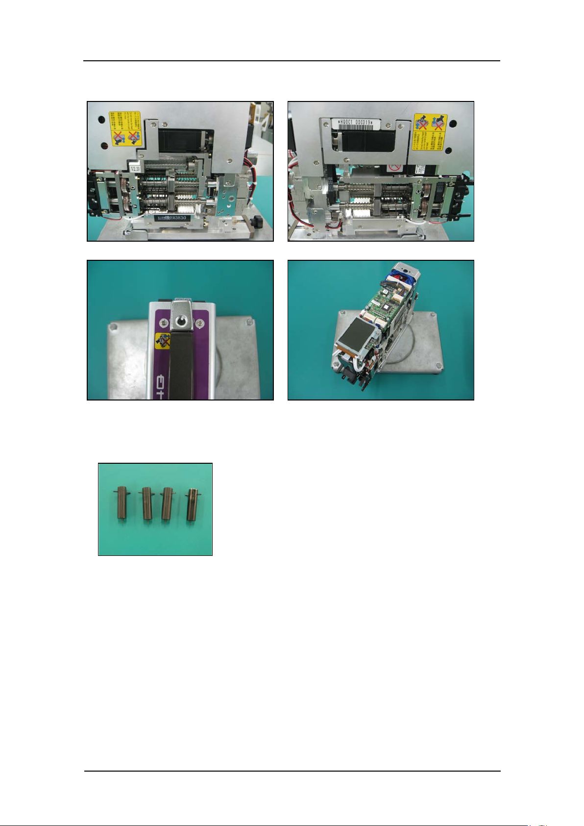
2. Remove the si de bolts.
Preparation at the module
1. Attach the jigs
2. Attach the h ead t o the modul e.
3. Tur n t he base main switch ON.
4. This complete s t he pr eparation for the ca m er a position ad justment.
CONFIDENTIAL
Edition 1.0 IPS Adjustment for Various Head Types on the Module
<G04Q head>
FK-9F50-74-0E 7- 3 FUJI CORPORATION
Component names and explanation of the adjustment modes
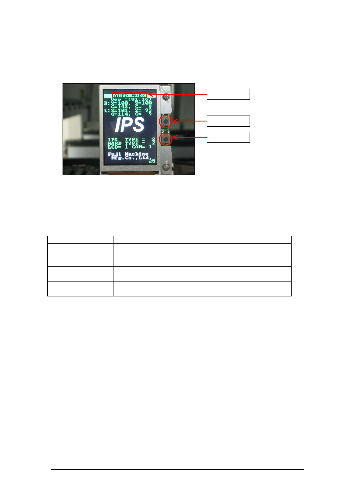
The names o f the LCD relay board comp onent s ar e given be low.
Mode na me: displays t he cur r ent ly selected adjustment mo de.
Back butt on: used to switch to a dif ferent mode from t he cur r ent ly selected mode.
Set button: us ed when saving or w hen select ing modes.
There are six a djustments modes as shown below. The adjustment s differ for each mode.
Mode na me
Contents
AUTO MODE
The initial screen displayed when power is supplied to the
head.
ADJ MODE
This mode is used to acc ess the 3 adj us tment mo des below.
ADJUSTMENT 1
Used for res ol ut ion and tilt adjustment.
ADJUSTMENT 2
Used for grayscale and curr ent value adjustment.
ADJUSTMENT 3
Used to chec k the field of vision.
CONFIGURATION
Used to set t he function settings.
Back butt on
Set button
Mode na me
CONFIDENTIAL