IPS adjustment on the modules.pdf - 第149页
Edition 1.0 IPS Adjustment for V ari ous Head T yp es on the Module < G04Q h ead > FK - 9F50 - 74 -0 E 7- 15 FUJI CORPORA T IO N 4. In the same w ay , confirm that the display changes as shown bel ow whe n blockin …
Edition 1.0 IPS Adjustment for Various Head Types on the Module
<G04Q head>
FK-9F50-74-0E 7-14 FUJI CORPORATION
Checking the field of vision
External l ig ht can affect the results so be sure to per form the procedure in a shaded area.
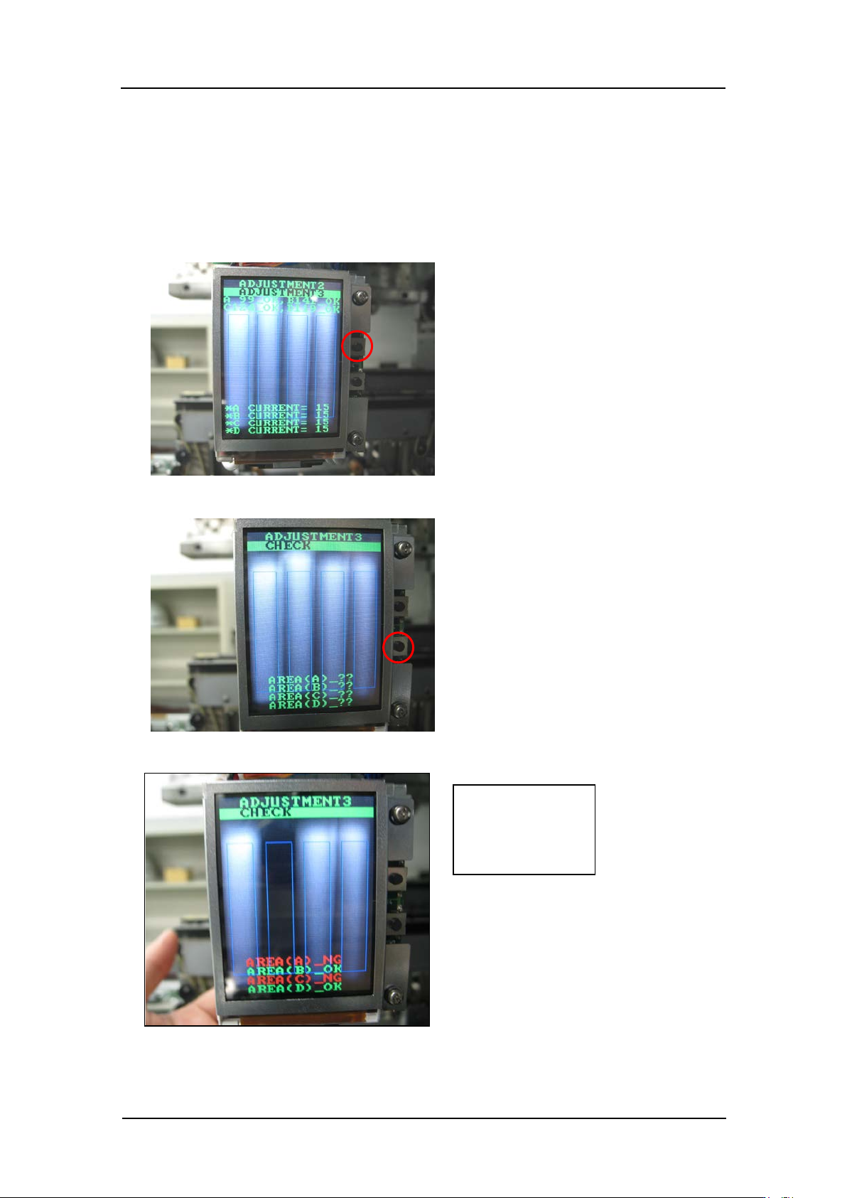
1. Continuing from the procedure above, press the upper button to display
“ADJUSTMENT 2 ADJUSTMENT 3”.
2. Press the lower button t o display “ ADJUSTMENT 3 CHECK”.
3. Block hold er A and conf irm that “AREA (A)_NG” and “AREA (C)_NG ” dis play.
Check:
AREA (A) _NG
AREA (C) _NG
CONFIDENTIAL
Edition 1.0 IPS Adjustment for Various Head Types on the Module
<G04Q head>
FK-9F50-74-0E 7-15 FUJI CORPORATION
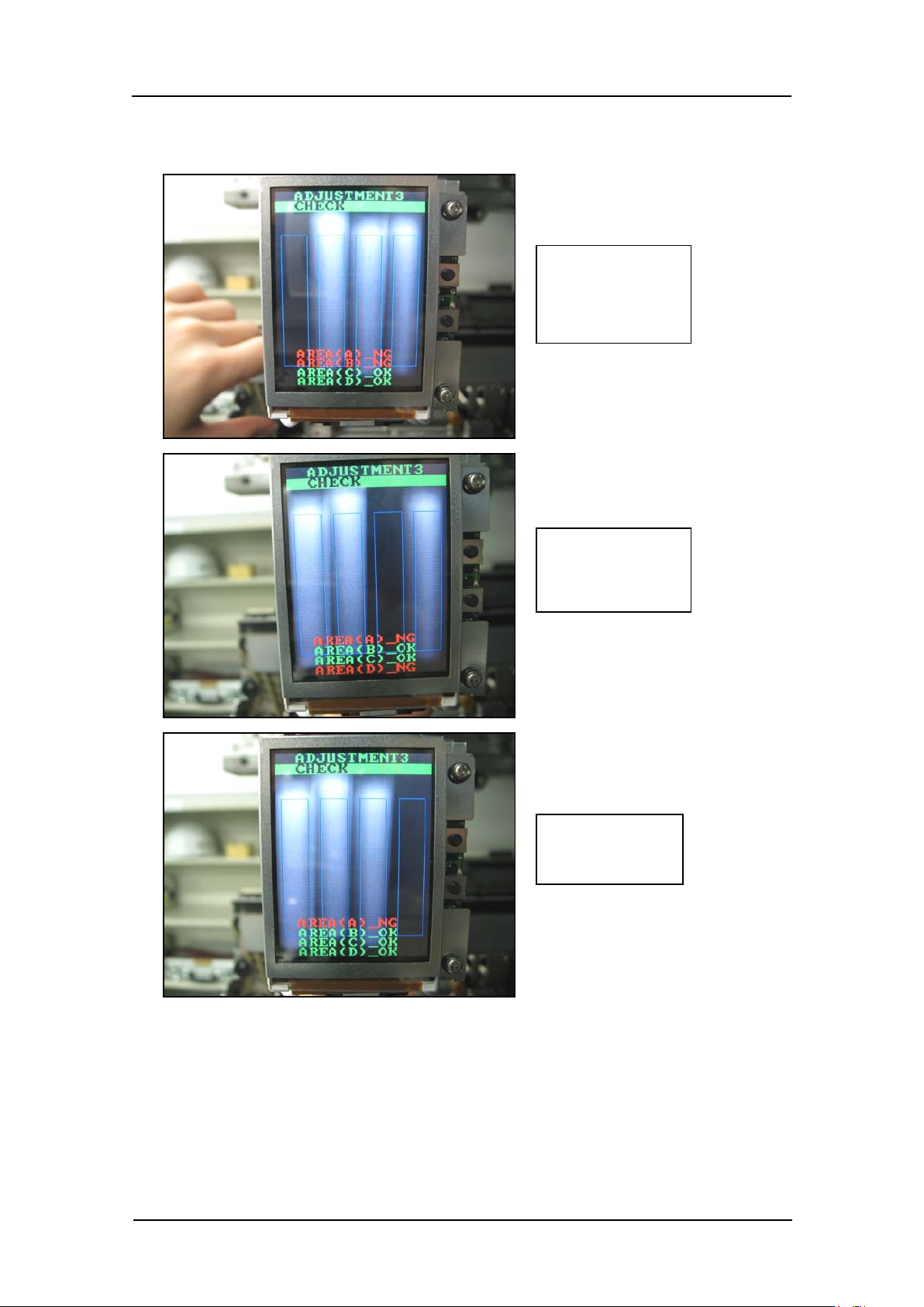
4. In the same way, confirm that the display changes as shown below when blocking
holders B~ D.
Check:
AREA (A) _NG
AREA (B) _NG
Check:
AREA (A) _NG
AREA (D) _NG
Check:
AREA (A) _NG
CONFIDENTIAL
Edition 1.0 IPS Adjustment for Various Head Types on the Module
<G04Q head>
FK-9F50-74-0E 7-16 FUJI CORPORATION
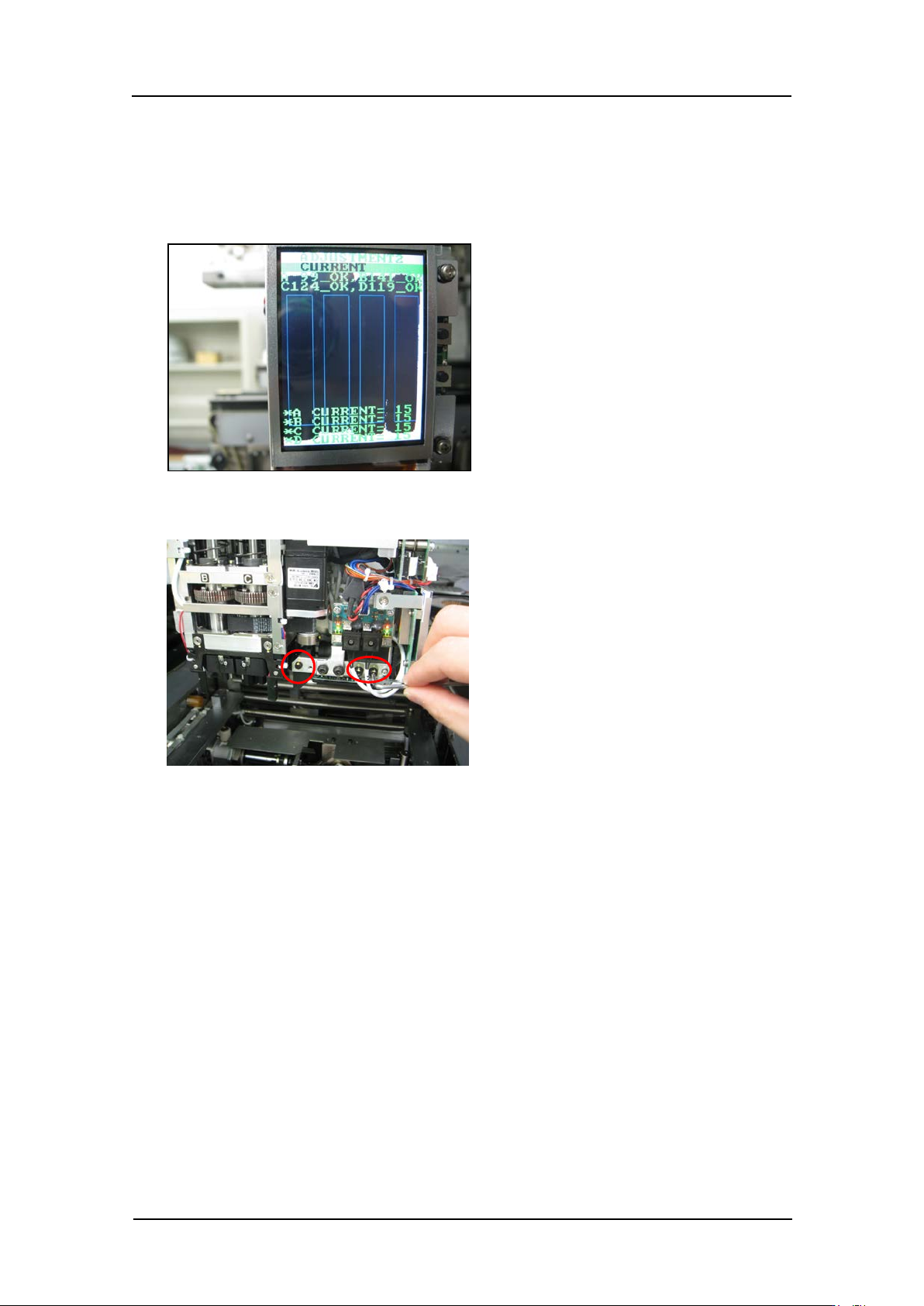
5. Press the upper and lower buttons simultaneously to reverse the LCD contrast, and
then check that there are no white areas within the blue rectangles. If there are white
areas within the blue rectangles, follow the procedure below to readjust the camera
position.
6. Use a wrench t o loosen the bolts shown in the following p hot o.
7. Adjust the position of the camera so that there are no white areas within the blue
rectangles on the LCD.
Caution: After this adjustment it is necessary to repeat “3.7 Adjusting the camera
installat i on position ” t o check the camera resoluti on, posi t i on and til t .
8. Tighten t he bolts with 0.5 Nm torque.
9. The field of v isi on check is now complete.
CONFIDENTIAL