IPS adjustment on the modules.pdf - 第157页
Edition 1 .0 IPS Adjustment for V arious Hea d T ypes on the Module < H12 L h ead > FK - 9F50 - 74 - 0E 8-3 FUJI CORPORA TION 9 After start ing communi cation, the c urrent se rv o counter of each axis ar e display…
Edition
1.0 IPS Adjustment for Various Hea d Types on the Module
<H12L head>
FK-9F50-74-0E 8-2 FUJI CORPORATION
Preparation on the modul e
1 Remove the covers.
2 Attach the n ozzle jigs to h older B and L.
3 In order to adjust the position of IPS camera, it is necessary to move to the R-ax is and
Q-axis to the original posit ion. The procedure is bel ow.
4 Attach the h ead to the mo dul e and turn the b ase power O N.
5 Push the START button at the main screen and immediately press the CYCLE STOP
button to stop the motion. Confirm that the R-axis has moved to its original position
(Holder A is in front).
6 Use the software “MotionAdjustmentTool” to check the servo counter of the head on
the module.
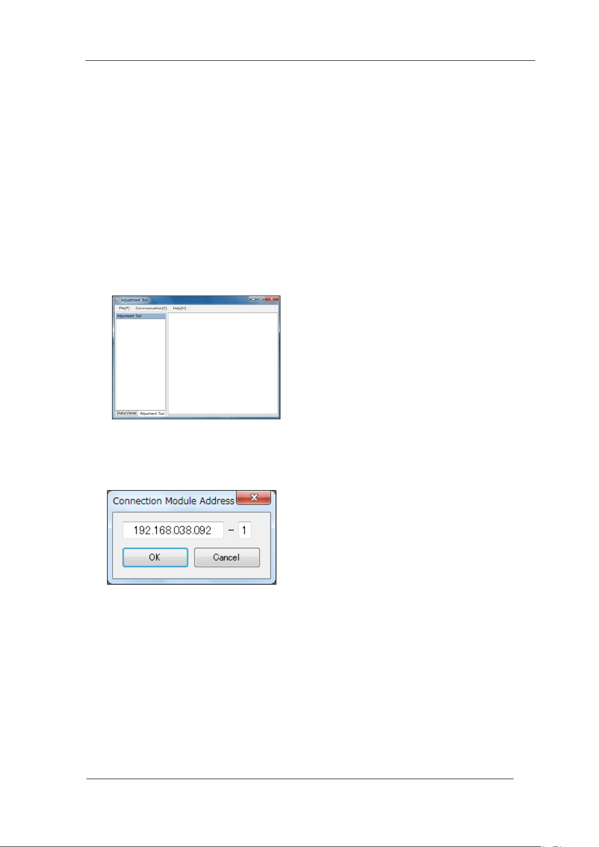
7 Startup MotionAdjustmentTool.
8 Sele ct [Communication] - [Connect]. Enter the IP address of the base and the module
number, and th en click [OK]
CONFIDENTIAL
Edition
1.0 IPS Adjustment for Various Hea d Types on the Module
<H12L head>
FK-9F50-74-0E 8-3 FUJI CORPORATION
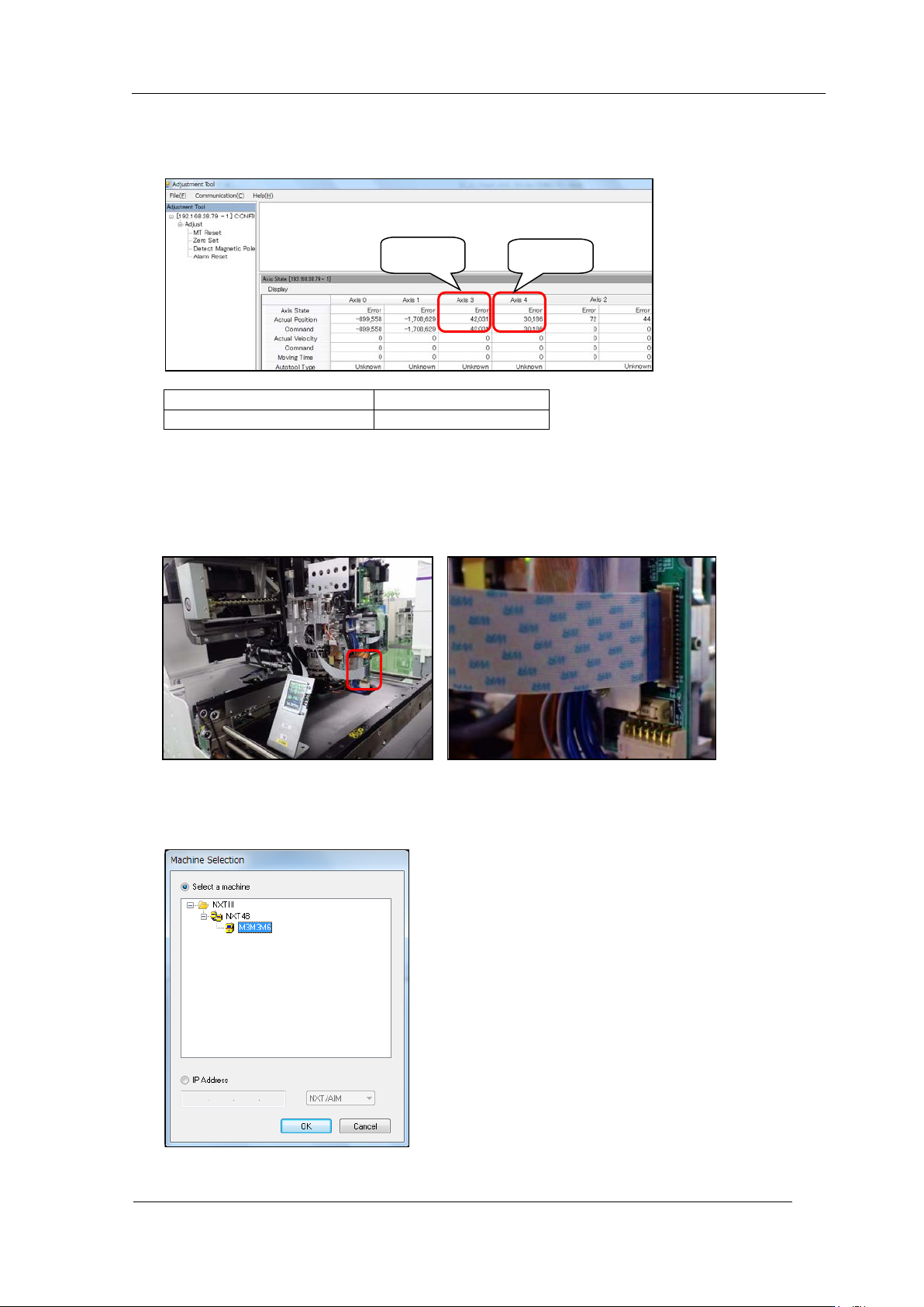
9 After starting communication, the current servo counter of each axis are
displayed. Recor d ser vo counters of Axis 3 (R-axis) and Axis 4 (Q-axis).
Original position of R-axis
0 to 60000 pulses
Original position of Q-axis
30000 ± 500 pulses
10 Press the PO WER but t on to enter s lee p mode and turn OFF the head power.
11 Attach the IPS monitor jig to the head. C onnect so that the blue side of the harness tip
faces outwar d (refer to the photo below).
12 Press the POWER button to wake.
13 Startup Equipm ent Ch eck and select M achine.
R-axis
Q-axis
CONFIDENTIAL
Edition
1.0 IPS Adjustment for Various Hea d Types on the Module
<H12L head>
FK-9F50-74-0E 8-4 FUJI CORPORATION
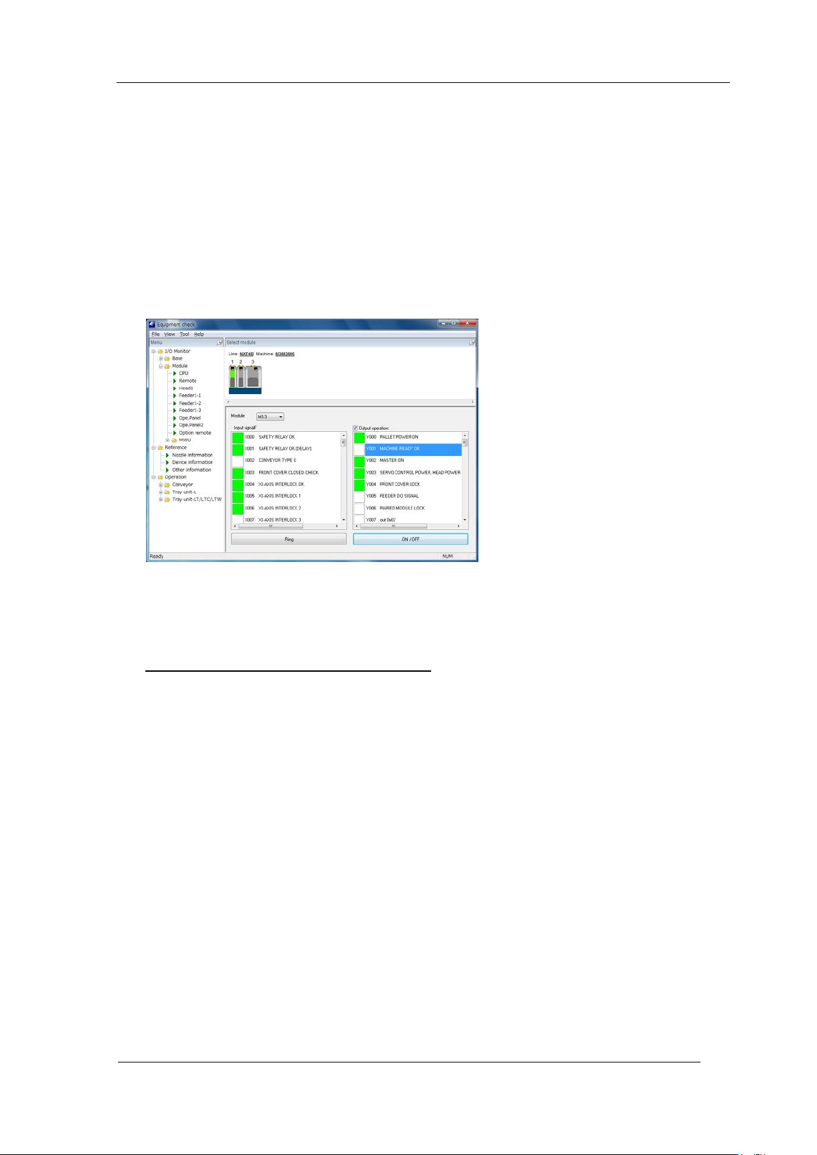
14 Select the mod ul e and select [ M odule] ⇒ [CPU].
15 Supply power t o t he head by t he follow in g pr ocedure .
● Put a check in [Output operation].
● Y003 SERVO CONTROL POWER HE AD POWER : ON
● Y002 MASTER ON : ON
● Y001 MACHINE READY OK : ON ⇒ OFF
● X000 SAFETY RELAY OK , X001 SAFETY OK (DEL AY) : ON
Confir m that t he I PS monitor jig scr een is displayed.
● Remove the chec k from [Output O per at ion].
16 Startup MotionAdjustmentTool. After starting communication, the current servo counter
of each axis are displayed. Move the R-axis (Axis 3) t o i ts original position (0 ~ 60000
pulses) and the Q-axis (Axis 4) to it s original position (30000 ± 500 pulses).
Be careful not to move from thi s position!
CONFIDENTIAL