IPS adjustment on the modules.pdf - 第166页
Edition 1 .0 IPS Adjustment for V arious Hea d T ypes on the Module < H12 L h ead > FK - 9F50 - 74 - 0E 8- 12 FUJI CORPORA TION 【 Individua l adjust ment meth od of R CURR ENT , L CURRENT 】 9. Display " CU R R…
Edition
1.0 IPS Adjustment for Various Hea d Types on the Module
<H12L head>
FK-9F50-74-0E 8-11 FUJI CORPORATION
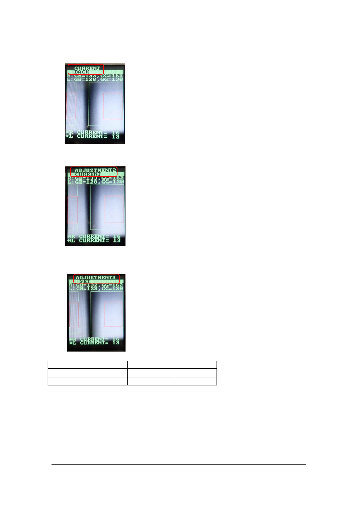
6. Once the value is within tolerance, press the upper button to display "CURRENT,
BACK".
7. Press the lower button t o display " A DJUSTMEN T 2, CURRENT".
8. Press the upper button to display "ADJUSTMENT 2, SET". Press the lower button to
save the set t ing.
Tolerance
Target value
GR, GL(grayscale value)
120
~
160
120
CURRENT(current value)
24mA or l ess
―
CONFIDENTIAL
Edition
1.0 IPS Adjustment for Various Hea d Types on the Module
<H12L head>
FK-9F50-74-0E 8-12 FUJI CORPORATION
【
Individual adjustment method of R CURRENT, L CURRENT
】
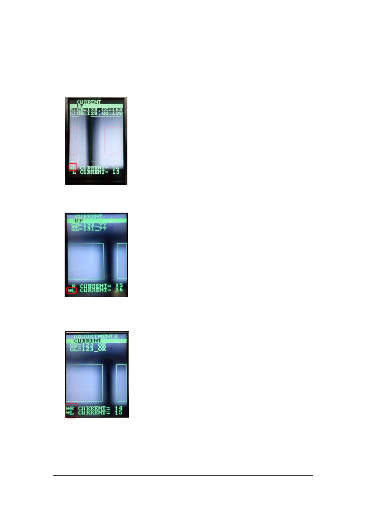
9. Display " CU R RENT, UP" or "CURRENT, DOWN" and hold dow n t he lower bu t t on.
10. “*“ is displayed only for R CURRENT. If you press the lower button in this state, you
can set the curr ent value of R only.
11. Hold down the lower button, then “*” is displayed on L CURRENT only. If you press
the lower butt on in this stat e, you can set the c ur rent value of L only.
12. Hold down the lower button, then “*” are displayed on both R and L CURRENT. I f you
press the low er but ton in this state, you can set the current value on both R and L.
CONFIDENTIAL
Edition
1.0 IPS Adjustment for Various Hea d Types on the Module
<H12L head>
FK-9F50-74-0E 8-13 FUJI CORPORATION
Checki ng t he Field of Vision
In this section, the field of vision is checked. The external light can influence the
result s, so be sure to perfor m t he proce dure with t he light bl ocke d.
1. Attach the jig nozzle to holder B an d L.
2. Use the MotionAdjustmentTool to check the servo counter and manually move the R -
axis to its original position ( t he A holder is in front) and the Q-axis to its original position.
(Refer to Section 4.2, step 6 to 9.)
R-axis origi nal position
0 to 60000 pulses
Q-axis o riginal position
30000 ± 500 pulses
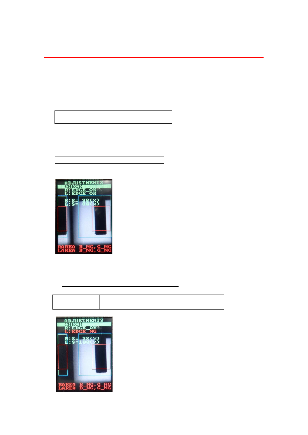
3. Press the upper button to switch to "ADJUSTMENT 3" and press the lower button to
confirm. Press the lower button to select “ADJUSTMENT 3 CHECK” to che ck the val ue
is within tolerance show n below.
4. In the “ADJUSTMENT3 CHECK” screen, block the right glass with some paper e t c . , (in
this case, the right side glass as seen from the front of the device) and then press the
lower button t o chec k the value is within to lerance show n below.
※ The image appears opposite to the left and right.
R : EDGE
=
OK
L : EDGE
=
OK
R : S
=
20
~
40 %
L : S
=
70
~
95 %
L
:
EDGE
=
NG
R
:
EDGE
=
OK
L:S
=
100%
R:S
=
The sa me v alue as w hen it is not blocked
CONFIDENTIAL