IPS adjustment on the modules.pdf - 第167页
Edition 1 .0 IPS Adjustment for V arious Hea d T ypes on the Module < H12 L h ead > FK - 9F50 - 74 - 0E 8- 13 FUJI CORPORA TION Checki ng t he Fi eld of Vision In this s ection, the fiel d of visi on is c hecked. T…
Edition
1.0 IPS Adjustment for Various Hea d Types on the Module
<H12L head>
FK-9F50-74-0E 8-12 FUJI CORPORATION
【
Individual adjustment method of R CURRENT, L CURRENT
】
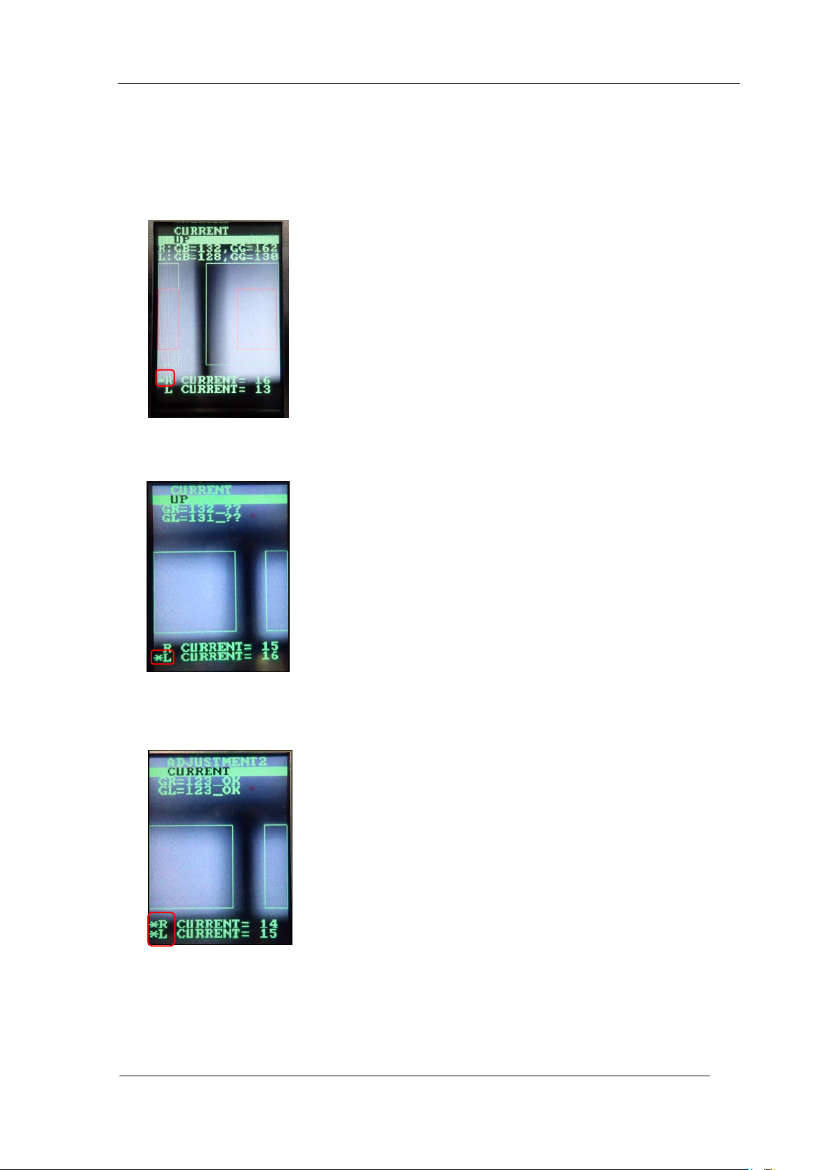
9. Display " CU R RENT, UP" or "CURRENT, DOWN" and hold dow n t he lower bu t t on.
10. “*“ is displayed only for R CURRENT. If you press the lower button in this state, you
can set the curr ent value of R only.
11. Hold down the lower button, then “*” is displayed on L CURRENT only. If you press
the lower butt on in this stat e, you can set the c ur rent value of L only.
12. Hold down the lower button, then “*” are displayed on both R and L CURRENT. I f you
press the low er but ton in this state, you can set the current value on both R and L.
CONFIDENTIAL
Edition
1.0 IPS Adjustment for Various Hea d Types on the Module
<H12L head>
FK-9F50-74-0E 8-13 FUJI CORPORATION
Checki ng t he Field of Vision
In this section, the field of vision is checked. The external light can influence the
result s, so be sure to perfor m t he proce dure with t he light bl ocke d.
1. Attach the jig nozzle to holder B an d L.
2. Use the MotionAdjustmentTool to check the servo counter and manually move the R -
axis to its original position ( t he A holder is in front) and the Q-axis to its original position.
(Refer to Section 4.2, step 6 to 9.)
R-axis origi nal position
0 to 60000 pulses
Q-axis o riginal position
30000 ± 500 pulses
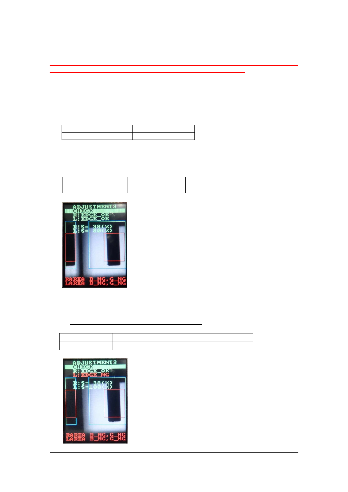
3. Press the upper button to switch to "ADJUSTMENT 3" and press the lower button to
confirm. Press the lower button to select “ADJUSTMENT 3 CHECK” to che ck the val ue
is within tolerance show n below.
4. In the “ADJUSTMENT3 CHECK” screen, block the right glass with some paper e t c . , (in
this case, the right side glass as seen from the front of the device) and then press the
lower button t o chec k the value is within to lerance show n below.
※ The image appears opposite to the left and right.
R : EDGE
=
OK
L : EDGE
=
OK
R : S
=
20
~
40 %
L : S
=
70
~
95 %
L
:
EDGE
=
NG
R
:
EDGE
=
OK
L:S
=
100%
R:S
=
The sa me v alue as w hen it is not blocked
CONFIDENTIAL
Edition
1.0 IPS Adjustment for Various Hea d Types on the Module
<H12L head>
FK-9F50-74-0E 8-14 FUJI CORPORATION
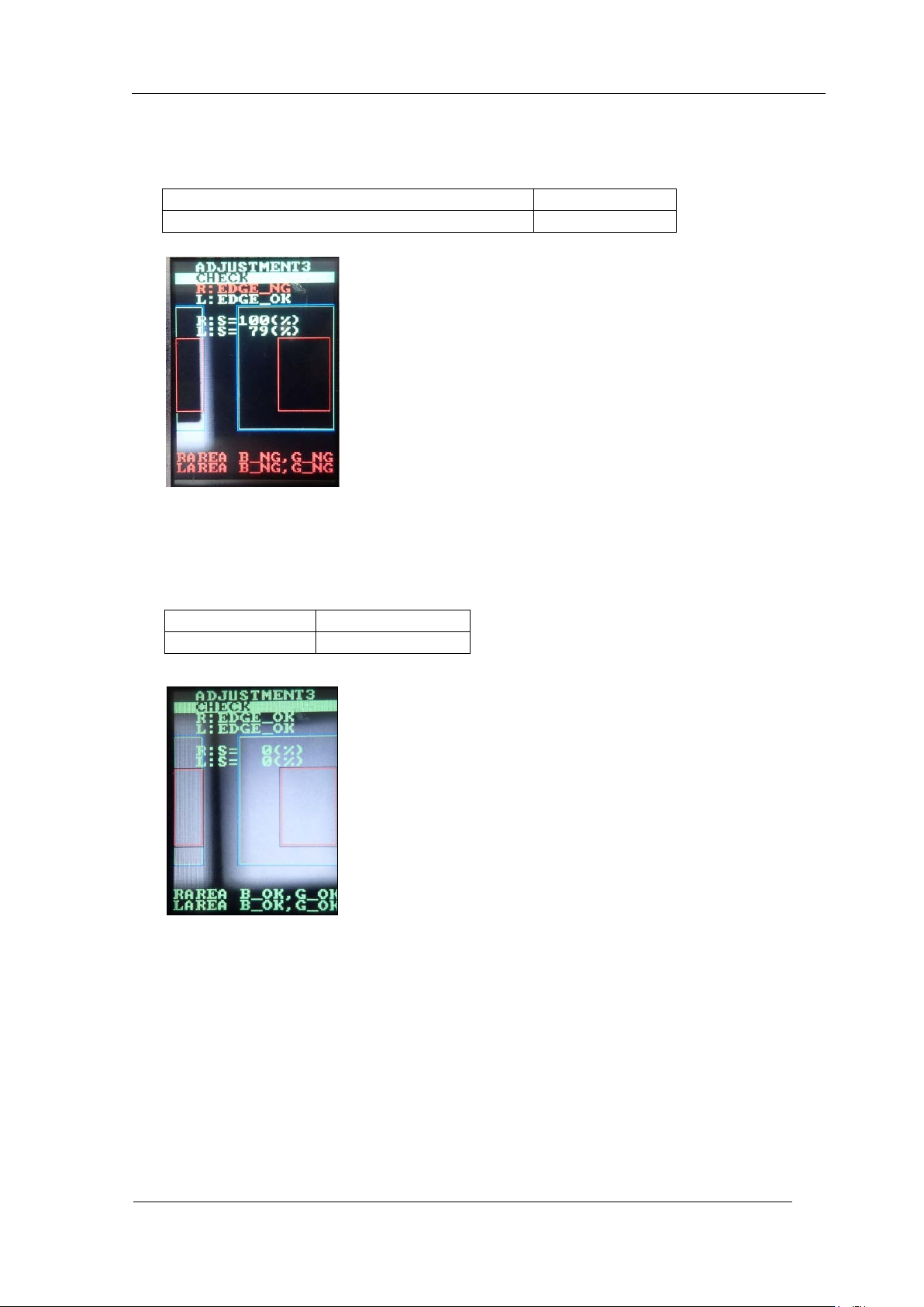
5. In the “ADJUSTMENT3 CHECK” screen, block the left glass with some paper etc., (in
this case, the left side glass as seen from the front of the device) and then press the
lower button t o check the v alue is within tolerance show n below.
6. Remov e t he jig nozzles.
7. In the “ADJUSTMENT3 CHECK” screen, press the lower button without blocking the
glasses to check the v alu e. The value sh oul d be shown like below.
L
:
EDGE
=
OK
R
:
EDGE
=
NG
L
:
S
=
The same value a s when it is not blocked
R
:
S
=
100%
R:EDGE
=
OK
L:EDGE
=
OK
R
:
S
=
0%
L
:
S
=
0%
CONFIDENTIAL