IPS adjustment on the modules.pdf - 第24页
E dition 1 .0 IPS Adjustment for V arious H ead T ypes on the Module < H24 head > FK - 9F50 - 74 - 0E 1- 12 FUJI CORPORA TION 【 A djust th e R CURR ENT and L CURRENT s eparately (IPS versi on 1.21 or l at er ) 】 1.…
Edition 1.0 IPS Adjustment for Various Head Types on the Module
<H24 head>
FK-9F50-74-0E 1-11
FUJI CORPORATION
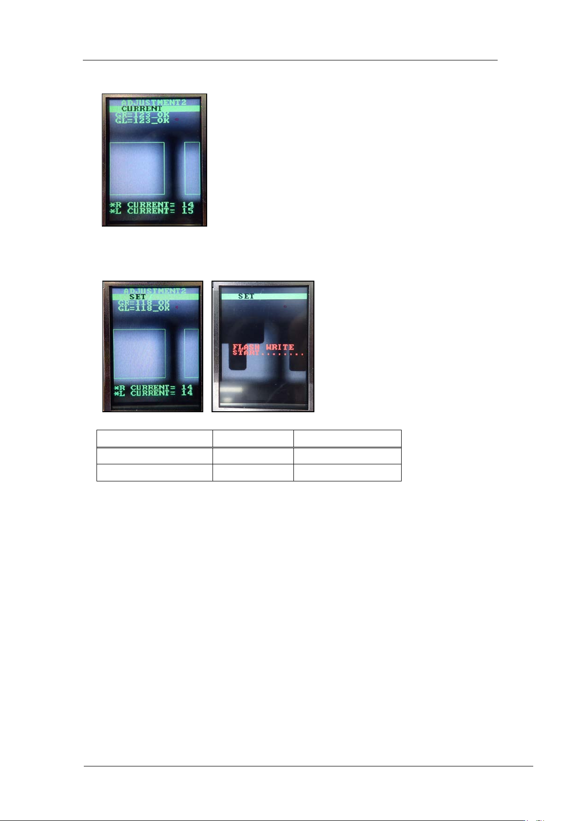
11. Press the lower button t o return to “ADJ USTM ENT 2 CURRENT”.
12. Press the upper button to display “ADJUSTMENT 2 SET” and then press the lower
button to save the sett ings.
Tolerance
Target
GR, GL (Gray value)
120~160
120
CURRENT
24mA or less
Same as tolerance
CONFIDENTIAL
Edition 1.0 IPS Adjustment for Various Head Types on the Module
<H24 head>
FK-9F50-74-0E 1-12
FUJI CORPORATION
【
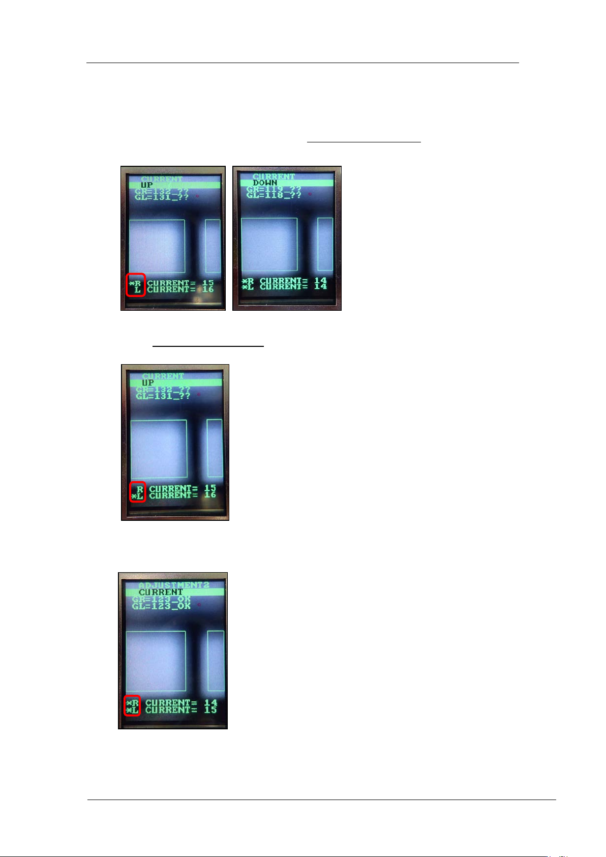
Adjust the R CURRENT and L CURRENT separately (IPS version 1.21 or l at er )
】
1. Press the lower but t on once, and t hen w it h [CURR ENT UP] or [C URRENT DOWN]
displayed, pr ess and hol d the lower button for 2 to 3 secon ds.
2. An asterisk mark * disp lays next to the R CUR RE NT value only. The lower butt on
can now be used t o adjust t he R C U RR ENT value.
3. Press and hold the lower but ton for 2 to 3 seconds. An asterisk mark * d isplays next
to the L CURRENT value only
. The lower but t on can now be us ed to adjust t he L
CURRE NT value.
4. Press and hold the lower but ton for 2 to 3 seconds. An asterisk mark * d isplays next
to both the R CURRENT and L CURRE NT values. The lower button can now be
used to adjust t he R CUR RE NT and L CURRENT values toget her.
CONFIDENTIAL
Edition 1.0 IPS Adjustment for Various Head Types on the Module
<H24 head>
FK-9F50-74-0E 1-13
FUJI CORPORATION
Checking the Fi eld of Vision
External light can influence the results, so be sure to perform the procedure in a shaded
area.
1. Attach the jig nozzles (2A G KN J001500) to syringe B and X.
2. While checking the R-axis servo count in MotionAjustmentTool, move the A holder to
the front of t he head.
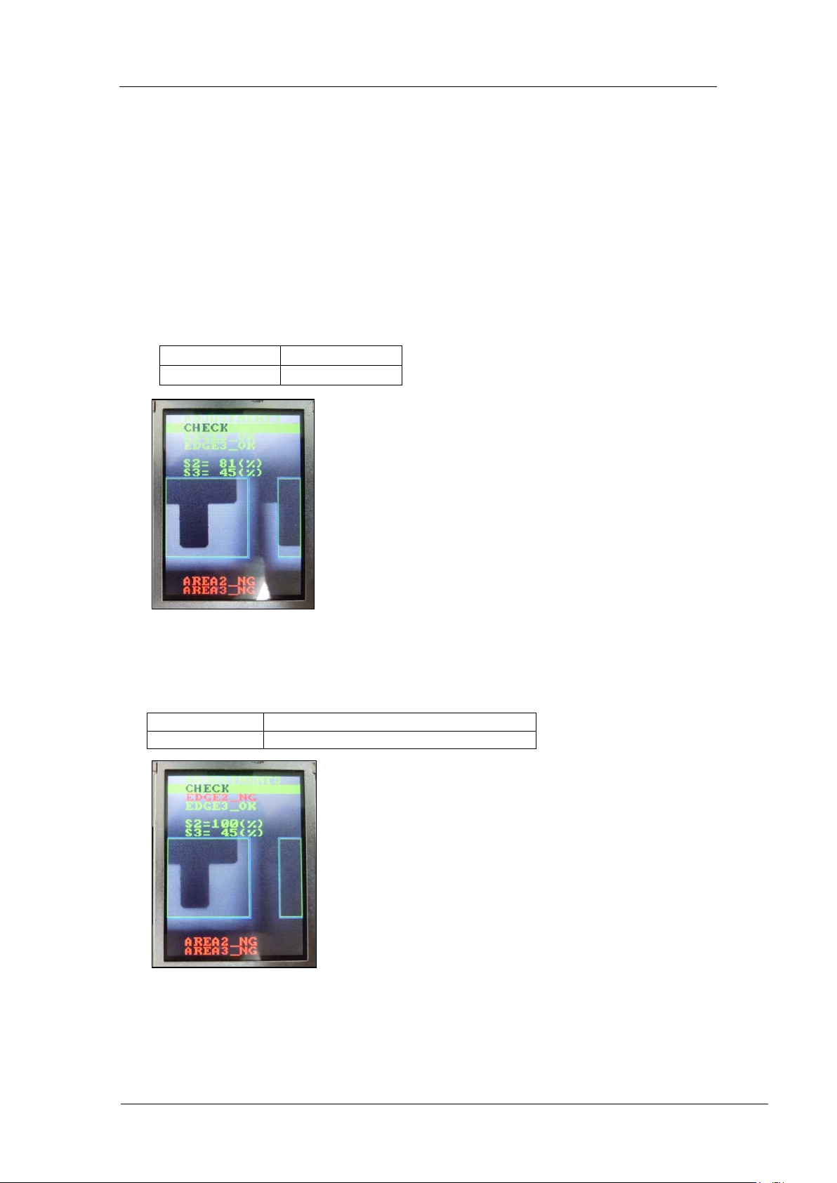
3. Press the upper button to change to “ADJUSTMENT 3” mode, and then press the
lower button to enter the adjustment mode. Press the lower button to select
“ADJUSTMENT 3 CHECK” to c heck the value is in the toleranc e shown below
4. In the “ADJUSTMENT3 CHECK” screen, block the right glass with some paper etc.,
and then press the lower button to check the value is in the tolerance shown below. (In
the example below, the right-hand glass as viewed from the front of the machine is
blocked).
EDGE 2 = OK
EDGE 3 = OK
S2 = 75~95%
S3 = 25~45%
EDGE2 = NG
EDGE3 = OK
S2 = 100%
S3 = same valu e as w hen not bloc k ed
CONFIDENTIAL