IPS adjustment on the modules.pdf - 第36页
E dition 1 .0 IPS Adjustment for V arious H ead T ypes on the Module <H24G/H24 S/H24A > FK - 9F50 - 74 -0E 2-2 FUJI CORPORA TION Component nam e s and e x pl anation of the a dj ustment modes Mode name: dis plays t…
Edition 1.0 IPS Adjustment for Various Head Types on the Module
<H24G/H24S/H24A>
FK-9F50-74-0E 2-1 FUJI CORPORATION
Chapter 2- H24G / H24S / H24A head IPS adjsutment
Camera position adjustment, current value (grayscale value)
adjustment and area check
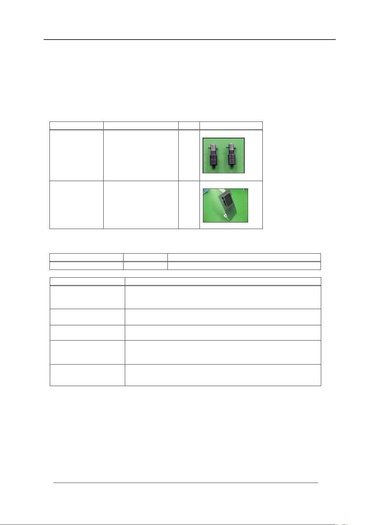
Required Jigs
Drawing No.
Name
Qty
Photo
2AGKNJ001500
IPS camera resolution
measurement jig
2
2AGTHJ004802
IPS Monitor Ji g
1
Required software
Inspection item
Tolerance
Camera resolution
check
L: X = 94~ 110
L: Z = 94~110
Center val ue
R: Xs = 380~ 400
(Target: 390) , Zp = 235~ 255 (Target : 245)
L: Xp = 80~ 100
(Target: 90
)
, Zp = 235~255(Target: 245)
Tilt
R: dX = 0~6 ( Target: 0) , dZ = 0~9 ( Target: 0)
L: dX = 0~ 6
(Target: 0), dZ = 0~9 ( Target: 0)
LED current adjustm ent
Area 2,3
Grays cale v a lue R
:
GB = 140~160, L
:
GB =140~160 (Target: 15
0)
CURRE NT v alue: 24 mA or less
LED current adjustm ent
Area 4
Grays cale v alue GB= 160
~
180,
CURRE NT v alue: 24 mA or less
Name
Drawing No.
Note
Motion Adjustment Tool
None
Install it from the NXT app lication CD-ROM.
CONFIDENTIAL
Edition 1.0 IPS Adjustment for Various Head Types on the Module
<H24G/H24S/H24A>
FK-9F50-74-0E 2-2 FUJI CORPORATION
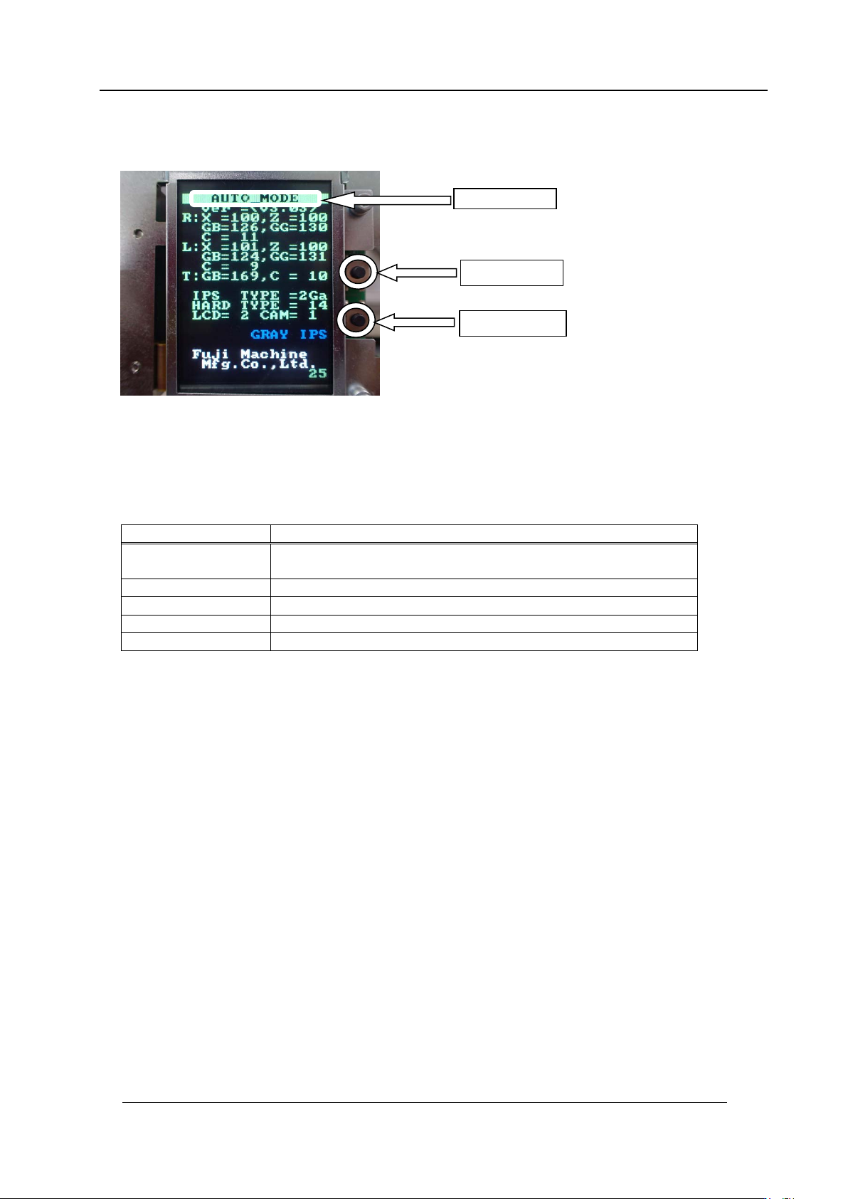
Component nam e s and e x planation of the a djustment modes
Mode name: displays t he cur r ent ly selected adjustment mode.
Back butt on: used t o switch t o a different mode from t he cur r ent ly selected mode.
Set button: us ed when saving or when selecting mo des.
Mode name
Contents
AUTO
MODE
The initial screen displayed when the power is supplied to the
head.
ADJ MODE
This mode is used to acce ss t he 3 adjustme nt modes below.
ADJUSTMENT 1
Used for res ol ut ion and tilt adjustment.
ADJUSTMENT 2
Used for gray scale and cu r r ent value adjustment.
ADJUSTMENT 3
Used to chec k the field of vision.
Note: Prior to use the IPSG board on the H24G, check that the configuration setting
is set as IPS TYPE = 2Ga, HA R D T YPE = 14.
Back butt on
Set button
Mode name
CONFIDENTIAL
Edition 1.0 IPS Adjustment for Various Head Types on the Module
<H24G/H24S/H24A>
FK-9F50-74-0E 2-3 FUJI CORPORATION
Preparation On the Module
1. Remove the covers.
2. Attach the jigs (2AGKNJ0 01500*) to holders B and X on the head.
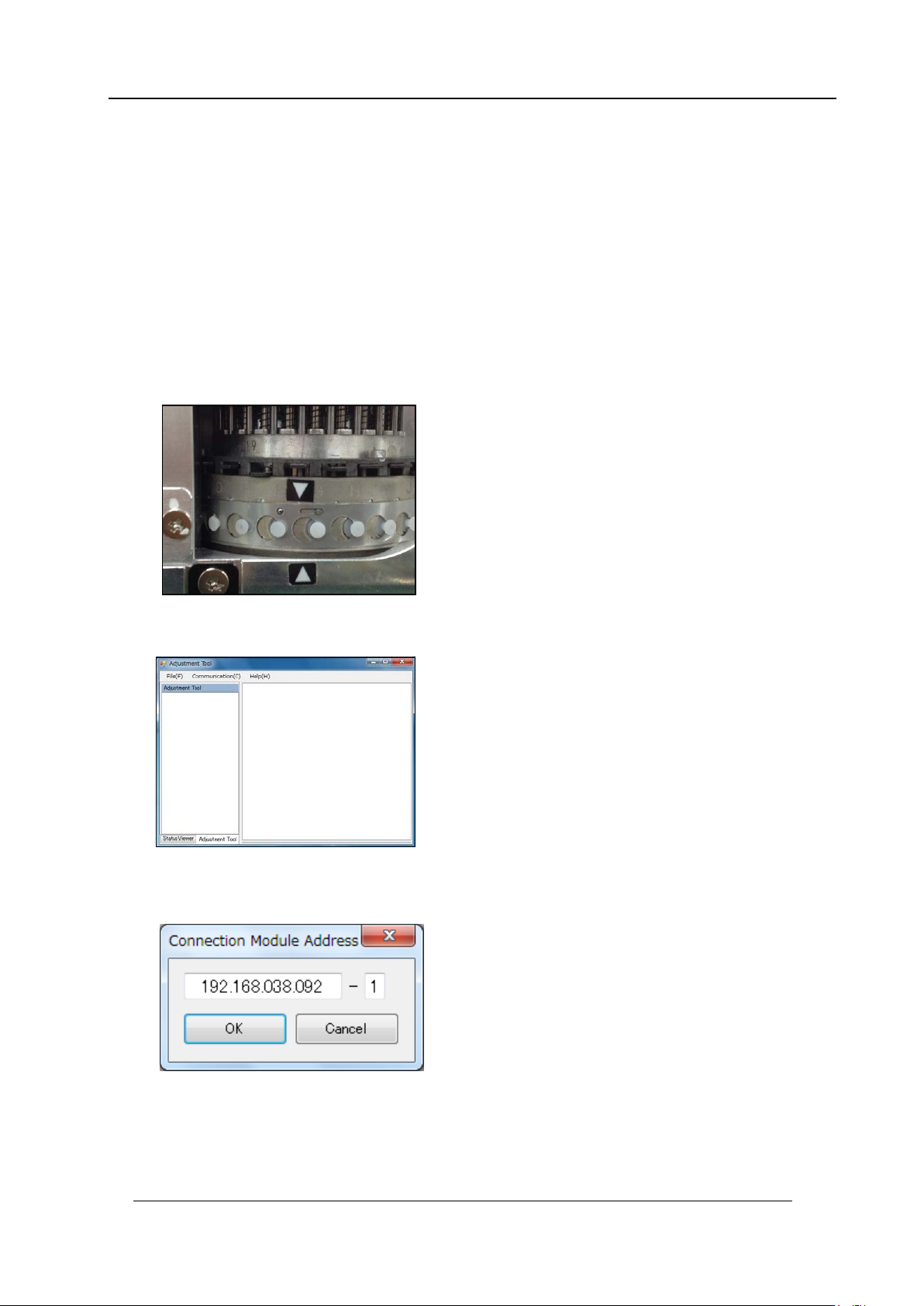
3. To adjust the IPS camera position, it is necessary to move the R-axis to the MT reset
position. The pr ocedure is explained below
4. Attach the head to t he module and t ur n t he base pow er O N.
5. After the machine wakes up, push the start button and then push the cycle stop button
immediately. After that, check that the R-axis h as been moved to the MT reset position.
6. Check the servo count er on the modu le using the Motion Adjust ment Tool.
7. Startup MotionAjustmentTool.
8. Enter the IP address of the base and t he module number, and then click [Connect].
CONFIDENTIAL