IPS adjustment on the modules.pdf - 第44页
E dition 1 .0 IPS Adjustment for V arious H ead T ypes on the Module <H24G/H24 S/H24A > FK - 9F50 - 74 -0E 2- 10 FUJI CORPORA TION 【 adjust t he R CURRE NT and L CURRENT s eparately 】 1. Press the upper b utton t o…
Edition 1.0 IPS Adjustment for Various Head Types on the Module
<H24G/H24S/H24A>
FK-9F50-74-0E 2-9 FUJI CORPORATION
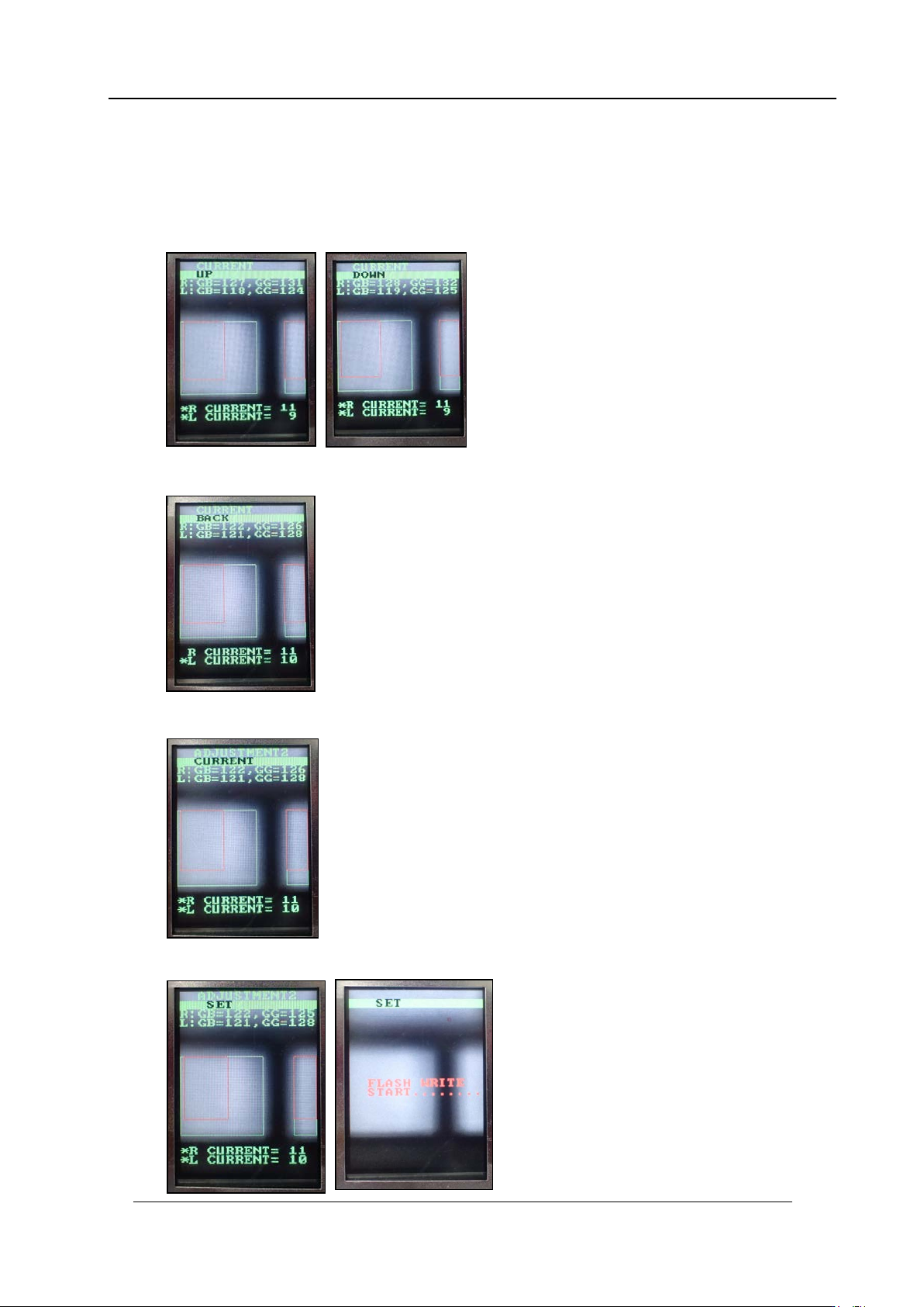
If the grayscale values are not w ithin the target val ues, adjust the m as shown bel ow.
7. Press the lower button to display “CURRENT UP” or “CURRENT DOWN”. When
raising the value, display “CURRENT UP” and press the lower button to adjust the
value. When lowering the value, display “CURRENT DOWN” and press the lower
button to adj ust the value.
8. Once the value is within the tolerance, press the upper button to display “CURRENT
BACK”.
9. Press the low er but t on t o return to “ADJUST M ENT 2 CURREN T” .
10. Press the upper button to display “ADJUSTMENT 2 SET” and then press the lower
button to save the sett ings.
CONFIDENTIAL
Edition 1.0 IPS Adjustment for Various Head Types on the Module
<H24G/H24S/H24A>
FK-9F50-74-0E 2-10 FUJI CORPORATION
【
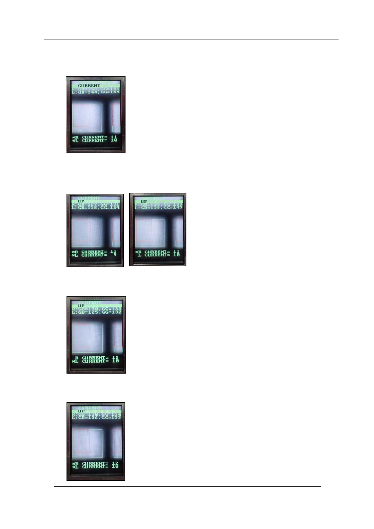
adjust the R CURRENT and L CURRENT separately
】
1. Press the upper button t o disp lay “ADJ US TMENT 2, CUR R EN T.
2. Press the lower button once, and then with [CURRENT UP] or [CURRENT DOWN]
displayed, press and hold the lower button for 2 to 3 seconds. An asterisk mark *
displays next to the R CURRENT value only. The lower button can now be used to
adjust the R CU R RENT value.
3. Press and hold the lower button for 2 to 3 seconds. An asterisk mark * displays next to
the L CURRENT value only. The lower button can now be used to adjust the L
CURRENT value.
4. Press and hold the lower button for 2 to 3 seconds. An asterisk mark * displays next to
both the R CURRENT and L CURRENT values. The lower button can now be used to
adjust the R CU R RENT and L CURRENT values together.
CONFIDENTIAL
Edition 1.0 IPS Adjustment for Various Head Types on the Module
<H24G/H24S/H24A>
FK-9F50-74-0E 2-11 FUJI CORPORATION
Checki ng t he Field of Vision
(
ADJUSTMENT3
)
External light can influence the results, so be sure to perform the procedure in a shaded
area.
1. Attach the jig nozzles (2A G KN J001500) to holder B and X.
2. Move the R-axis to its calibration data position (R ef er ence value: 30000 ± 3000 pulses).
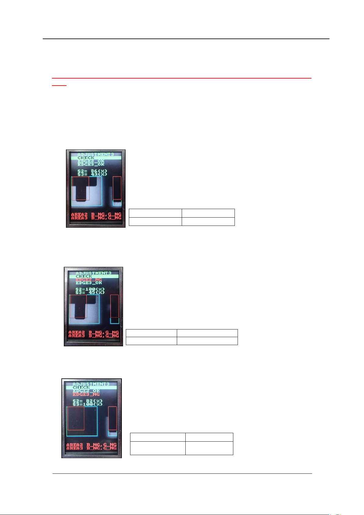
3. Press the upper button to change to “ADJUSTMENT 3” mode, and then press the
lower button to enter the adjustment mode. Press the lower button to select
“ADJUS TM E NT 3 C HE CK” to check the value is in the tolera nce shown be low
4. In the “ADJUSTMENT3 CHECK” screen, block the right glass with some paper etc.,
and then press the lower button to check the value is in the tolerance shown below. (In
the example below, the right-hand glass as viewed from the front of the machine is
blocked).
5. In the “ADJUSTMENT3 CHECK” screen block the left-hand glass with some paper and
then press the lower button to check the value is in the tolerance below. (In the
example b elow t he left-hand gl ass as viewed from the fro nt of the machine is blocked) .
6. Remov e t he jig nozzles (2AG KNJ001 500).
EDGE 2 = OK
EDGE 3 = OK
S2 = 75~95%
S3 = 25~45%
EDGE2 = NG
EDGE3 = OK
S2 = 100%
S3 = 25 to 45%
EDGE2
=
OK
EDGE3
=
NG
S2
=
75
~
95%
S3
=
100%
CONFIDENTIAL