IPS adjustment on the modules.pdf - 第46页
E dition 1 .0 IPS Adjustment for V arious H ead T ypes on the Module <H24G/H24 S/H24A > FK - 9F50 - 74 -0E 2- 12 FUJI CORPORA TION 7. When display ing “ADJU STMENT 3 CHECK” and pressing the lower but ton without bl…
Edition 1.0 IPS Adjustment for Various Head Types on the Module
<H24G/H24S/H24A>
FK-9F50-74-0E 2-11 FUJI CORPORATION
Checki ng t he Field of Vision
(
ADJUSTMENT3
)
External light can influence the results, so be sure to perform the procedure in a shaded
area.
1. Attach the jig nozzles (2A G KN J001500) to holder B and X.
2. Move the R-axis to its calibration data position (R ef er ence value: 30000 ± 3000 pulses).
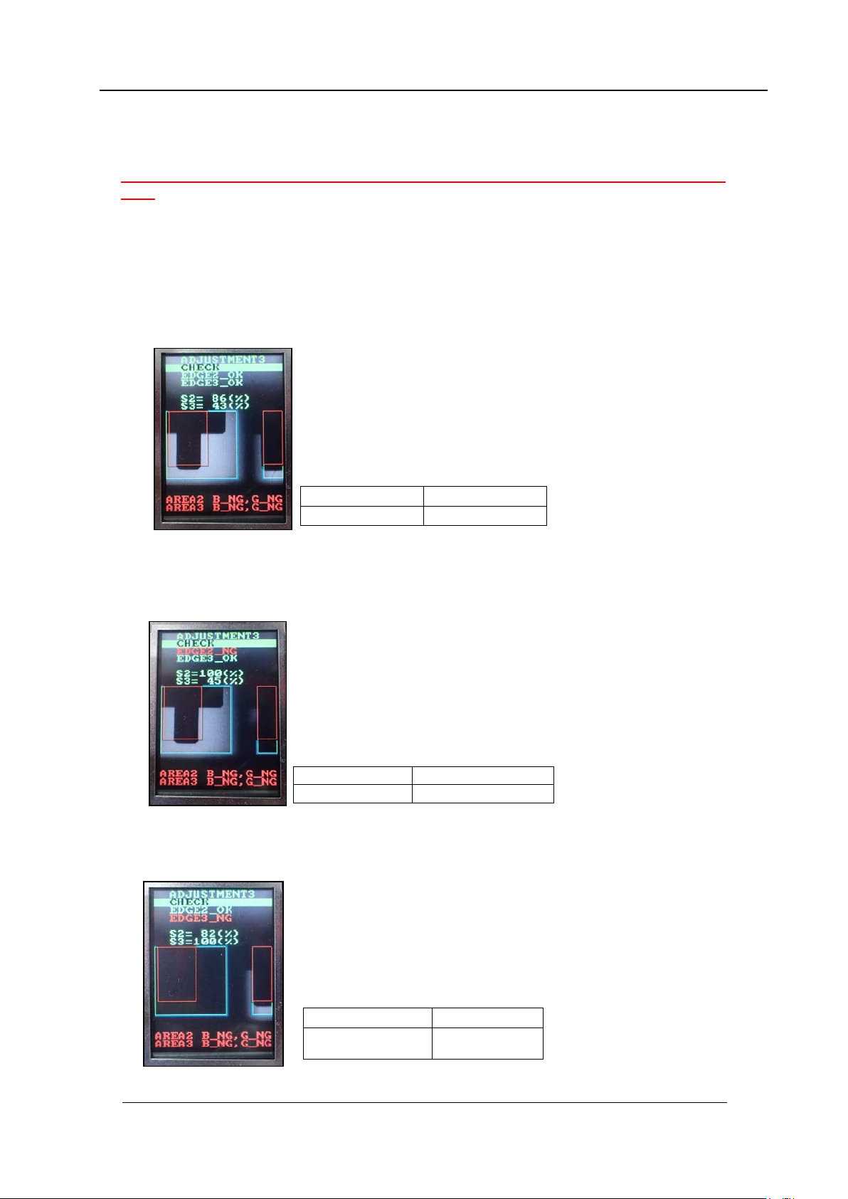
3. Press the upper button to change to “ADJUSTMENT 3” mode, and then press the
lower button to enter the adjustment mode. Press the lower button to select
“ADJUS TM E NT 3 C HE CK” to check the value is in the tolera nce shown be low
4. In the “ADJUSTMENT3 CHECK” screen, block the right glass with some paper etc.,
and then press the lower button to check the value is in the tolerance shown below. (In
the example below, the right-hand glass as viewed from the front of the machine is
blocked).
5. In the “ADJUSTMENT3 CHECK” screen block the left-hand glass with some paper and
then press the lower button to check the value is in the tolerance below. (In the
example b elow t he left-hand gl ass as viewed from the fro nt of the machine is blocked) .
6. Remov e t he jig nozzles (2AG KNJ001 500).
EDGE 2 = OK
EDGE 3 = OK
S2 = 75~95%
S3 = 25~45%
EDGE2 = NG
EDGE3 = OK
S2 = 100%
S3 = 25 to 45%
EDGE2
=
OK
EDGE3
=
NG
S2
=
75
~
95%
S3
=
100%
CONFIDENTIAL
Edition 1.0 IPS Adjustment for Various Head Types on the Module
<H24G/H24S/H24A>
FK-9F50-74-0E 2-12 FUJI CORPORATION
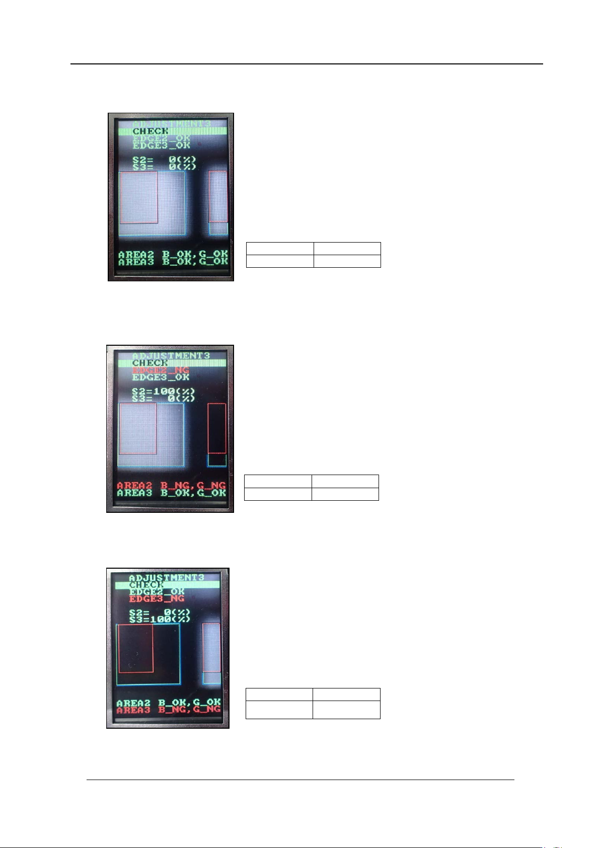
7. When displaying “ADJUSTMENT3 CHECK” and pressing the lower button without
blocking the glasses, check the v alu e. The value sho uld be shown li ke bl ow.
8. In the “ADJUSTMENT3 CHECK” screen block the right-hand glass with some paper
and then press the lower button to check the value is in the tolerance below. (In the
example below the right-hand glass as viewed from the front of the machine is
blocked).
9. In the “ADJUSTMENT3 CHECK” screen block the left-hand glass with some paper and
then press the lower button to check the value is in the tolerance below. (In the
example b elow the lef t-hand gl ass as viewed from the fro nt of the machine is blocked).
AREA2=OK
AREA3=OK
S2=0%
S3=0%
AREA2=NG
AREA3=OK
S2=100%
S3=0%
AREA2=OK
AREA3=NG
S2=0%
S3=100%
CONFIDENTIAL
Edition 1.0 IPS Adjustment for Various Head Types on the Module
<H24G/H24S/H24A>
FK-9F50-74-0E 2-13 FUJI CORPORATION
Adjusting the Nozzle Existence Curre nt ( Grayscale value)
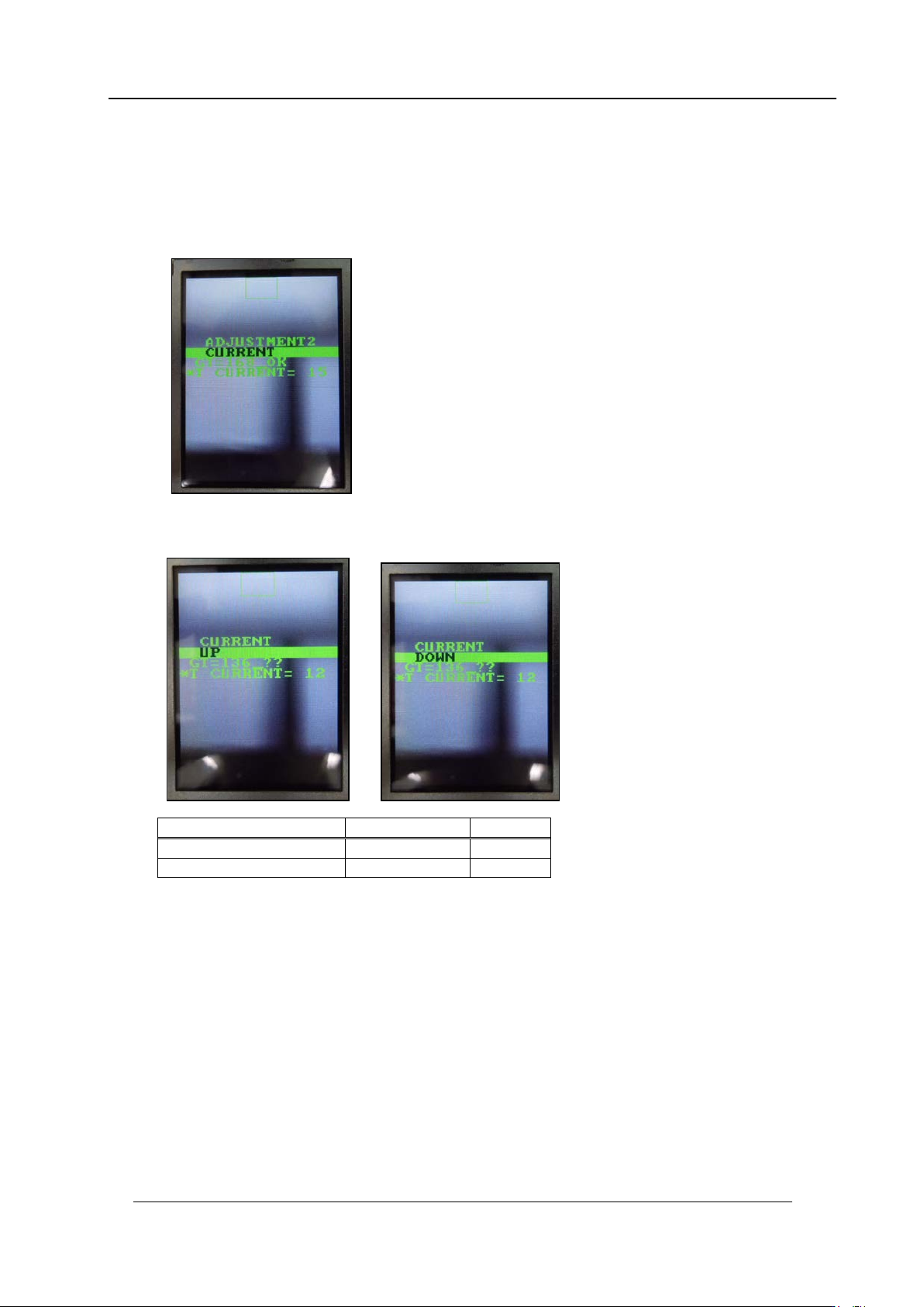
1. Press the upper button to select “ADJUSTMENT 3 BACK” and then press the lower
button to change to “A DJ US TMENT 2 CU R RE N T” .
2. Press and ho ld t he lower button to chan ge to area 4 adjustment mode.
3. Press the lower button to display “CURRENT UP” or “CURRENT DOWN”, and then
adjust the cur r ent value.
4. Rotate the R-axis through one full rotation and confirm that there is no position where
the variation in the grayscale values (GT) is extreme. If the value is too big, check the
fluorescent status. I f it i s dirty, clean or replace it as necessar y.
5. Press the up per but t on to display “CURR ENT BACK”.
Tolerance
Target
Grays cale v alues (GT)
160~180
180
CURRENT
24mA or less
CONFIDENTIAL