IPS adjustment on the modules.pdf - 第58页
Edition 1.0 IPS Adjustment for Various Head Types on the Modul e <DX h ead> FK - 9F50 - 74 -0E 3-4 FUJI CORPORAT ION 11. Pu sh the upper button t o ma ke t he settings sh own bel ow . 12. Pu sh the lower butt on t …
Edition
1.0 IPS Adjustment for Various Head Types on the Module
<DX head>
FK-9F50-74-0E 3-3 FUJI CORPORATION
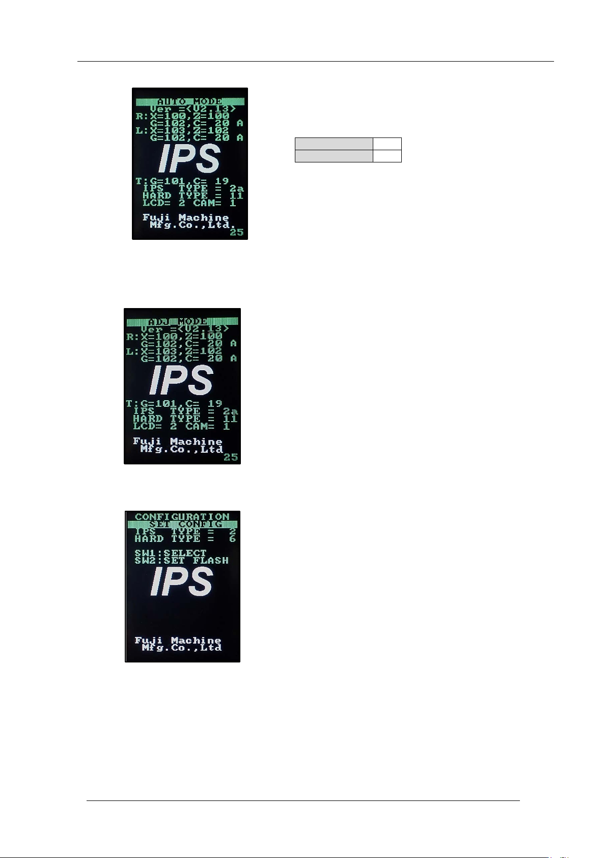
7. Check the co nfiguratio n settings are set as show n below.
8. If you need to change the set t ings, f ollow the pro c edure below.
9. Hold down t he low er but t on to enter “ADJ MODE”.
10. Push the upper and lower but tons togeth er to enter the “ CONFIG U RATION” screen.
IPS
TYPE
2a
HARD TYPE
11
CONFIDENTIAL
Edition
1.0 IPS Adjustment for Various Head Types on the Module
<DX head>
FK-9F50-74-0E 3-4 FUJI CORPORATION
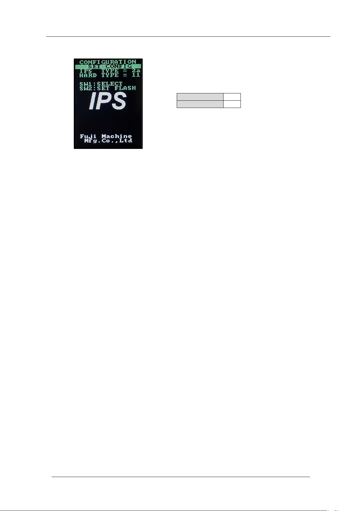
11. Push the upper button t o ma ke the settings shown bel ow.
12. Push the lower butt on t o save the sett ings.
13. After changing the settings, be sure to turn OFF the module. (It is necessary to reboot
the head.)
14. T ur n ON the mod ule power.
15. Push the start but ton and then push the cy cle st op button i m med iately.
16. The power is su pplied to the DX head.
IPS TYPE
2a
HARD TYPE
11
CONFIDENTIAL
Edition
1.0 IPS Adjustment for Various Head Types on the Module
<DX head>
FK-9F50-74-0E 3-5 FUJI CORPORATION
3.3 I P S uni t bri ghtness adjus t m e nt
1. Close the front cover and release the emergency stop button.
2. Push the star t button and t hen push the cy c le stop button i m med iately.
3. Startup Motion Adjustment Tool.
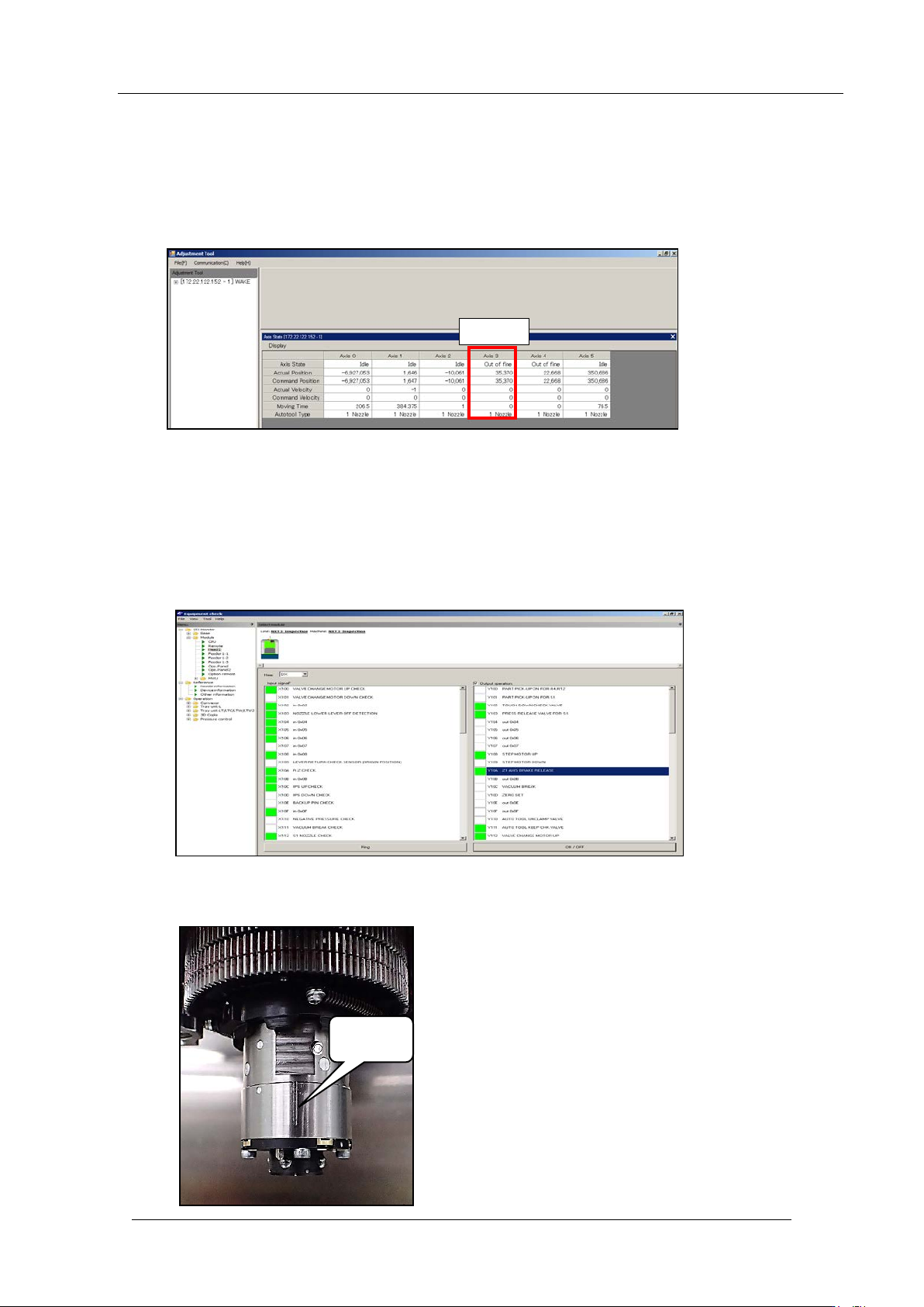
4. Record the R-axis (Axis3) count er valu e.
5. Push the emergency stop button and move the XY robot (head) towards the device pallet
side by hand.
6. Use Equip m ent Check I/O monitor to turn ON [Y10A Z1AXIS BRAKE RELEASE].
Note: The Z-axis lowers down by its ow n weight. Be careful it does not interfere with the
other parts .
7. Lower the Z 1-axis by hand, and t hen set the R-axis so the vert ical groove is at the front
as shown bel ow.
Vertical
groove
R-axis
R Axis
CONFIDENTIAL