IPS adjustment on the modules.pdf - 第60页
Edition 1.0 IPS Adjustment for Various Head Types on the Modul e <DX h ead> FK - 9F50 - 74 -0E 3-6 FUJI CORPORAT ION 8. T urn OF F [ Y10A Z1AXIS BRAKE RELE A SE ]. 9. T urn ON [ Y1 10 AU TO T OOL UNCLAMP ]. 10. Att…
Edition
1.0 IPS Adjustment for Various Head Types on the Module
<DX head>
FK-9F50-74-0E 3-5 FUJI CORPORATION
3.3 I P S uni t bri ghtness adjus t m e nt
1. Close the front cover and release the emergency stop button.
2. Push the star t button and t hen push the cy c le stop button i m med iately.
3. Startup Motion Adjustment Tool.
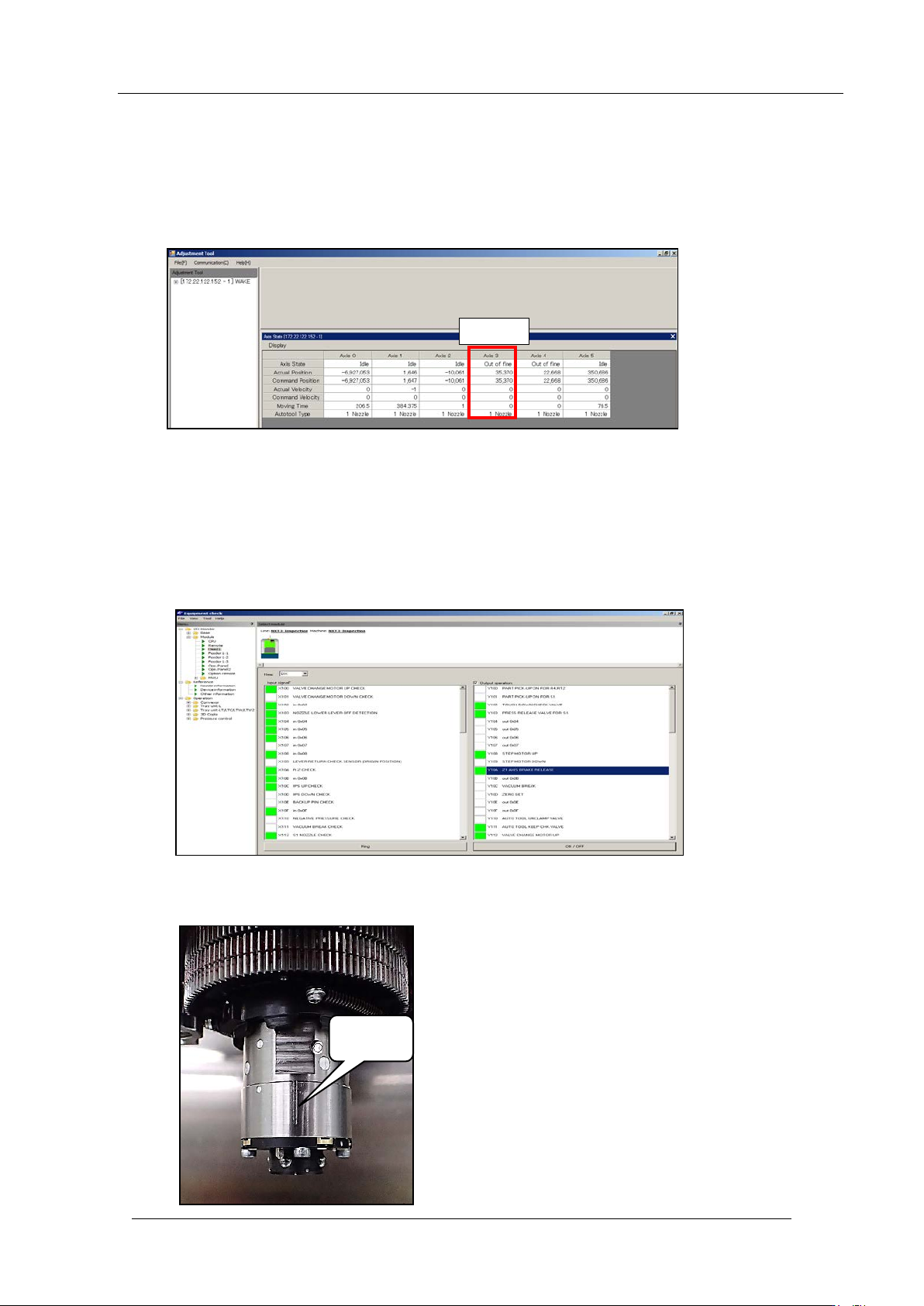
4. Record the R-axis (Axis3) count er valu e.
5. Push the emergency stop button and move the XY robot (head) towards the device pallet
side by hand.
6. Use Equip m ent Check I/O monitor to turn ON [Y10A Z1AXIS BRAKE RELEASE].
Note: The Z-axis lowers down by its ow n weight. Be careful it does not interfere with the
other parts .
7. Lower the Z 1-axis by hand, and t hen set the R-axis so the vert ical groove is at the front
as shown bel ow.
Vertical
groove
R-axis
R Axis
CONFIDENTIAL
Edition
1.0 IPS Adjustment for Various Head Types on the Module
<DX head>
FK-9F50-74-0E 3-6 FUJI CORPORATION
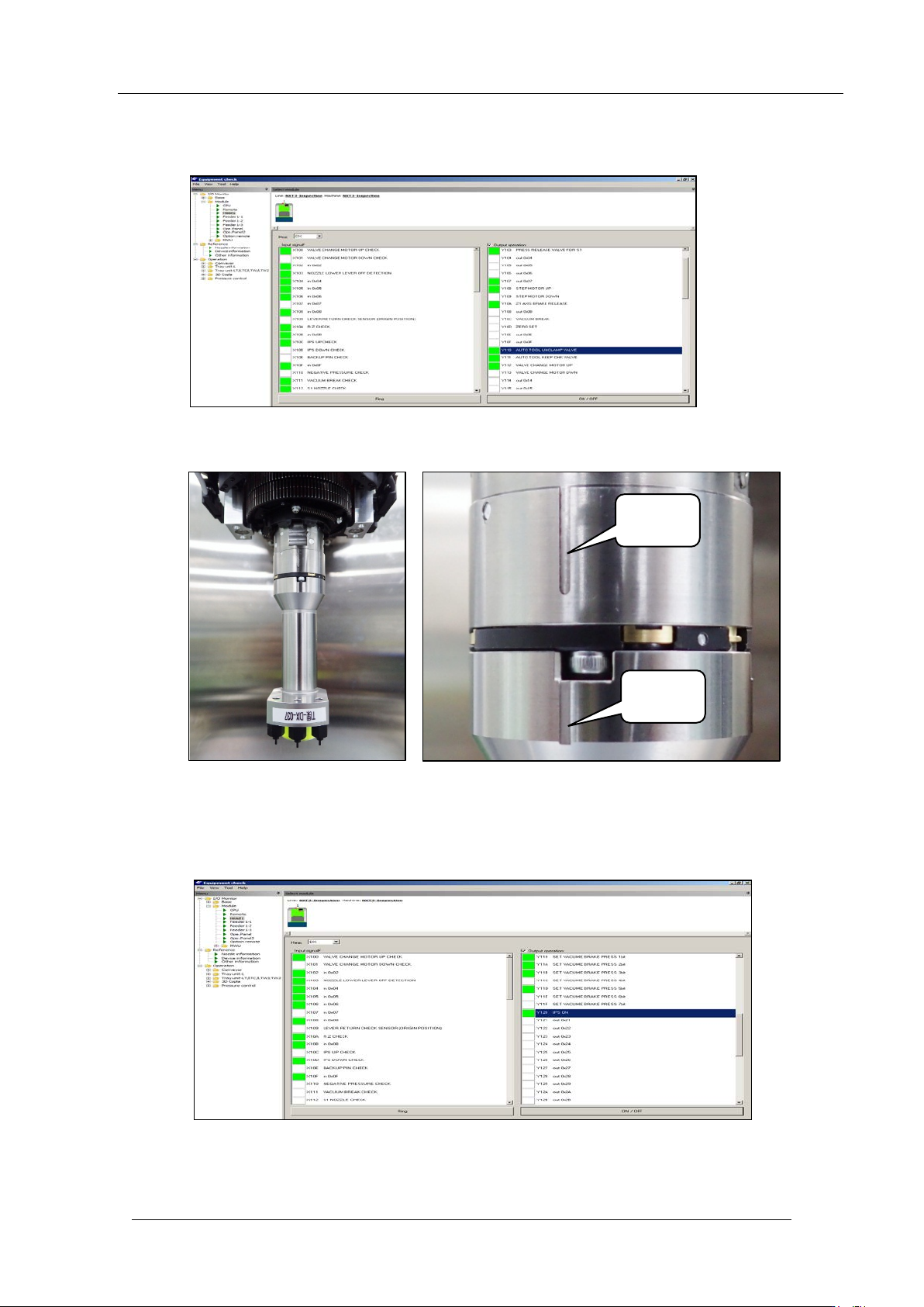
8. Turn OF F [Y10A Z1AXIS BRAKE RELEASE].
9. Turn ON [Y110 AUTO TOOL UNCLAMP].
10. Attach the IPS adjustment jig to the auto-tool clamper so the line on the jig is aligned
with the line on t he clamper, and then turn OFF [Y1 10 AUTO TOOL UNCLAMP].
11. Check the R-axis (Axis 3) servo counter value using Motion Adjustment T ool. Rotate the
R-axis by hand so it become s t he value recor ded in Step 4.
12. T ur n ON [Y120 I PS ON] to lower the IP S unit.
Vertical
groove
Vertical
groove
CONFIDENTIAL
Edition
1.0 IPS Adjustment for Various Head Types on the Module
<DX head>
FK-9F50-74-0E 3-7 FUJI CORPORATION
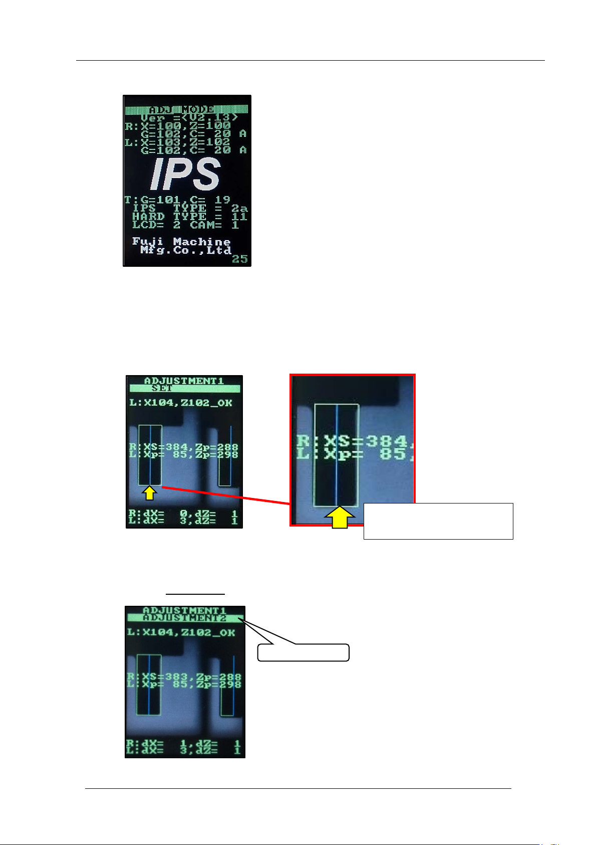
13. On the IPS monit or, hold down the low er but t on t o enter “ADJ MO DE”.
14. Push the lower button once to enter “ AD JUSTME N T1”.
15. Move the Z1-axis to the IPS vision processing position. Use Equipment Check I/O
monitor to turn ON [Y10A Z1AXIS BRAKE RELEASE].
16. Raise the Z1-axis so the jig displays on the IPS monitor as shown below. Align the
bottom edge of n ozzle with the green frame.
17. Turn OFF [Y10A Z1AXIS BRAKE RELEASE].
18. Push the upper butt on
once to select “ AD JUSTME NT 2” .
ADJUSTMENT 2
Align the bot t om edge of the
nozzle with the gr een frame.
CONFIDENTIAL