IPS adjustment on the modules.pdf - 第84页
Edition 1 .0 IPS Adjustment for V arious H ead T ypes on the Module <V12 h ead> FK - 9F50 -74-0E 4-8 FUJI CORPORA TION Adjusting t he c a mer a ins t al l ation posit i on (ADJUSTMENT1) 1. Press the upper a nd lowe…
Edition 1.0 IPS Adjustment for Various Head Types on the Module
<V12 head>
FK-9F50-74-0E
4-7
FUJI CORPORATION
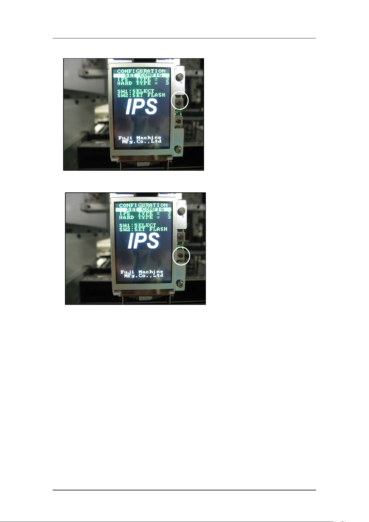
4. Press the upper button t o set “IPS TY PE” and “HARD TYPE” to 2.
5. Press the low er but t on t o comp lete the setti ng.
CONFIDENTIAL
Edition 1.0 IPS Adjustment for Various Head Types on the Module
<V12 head>
FK-9F50-74-0E
4-8
FUJI CORPORATION
Adjusting t he c a mer a ins t al lation posit ion (ADJUSTMENT1)
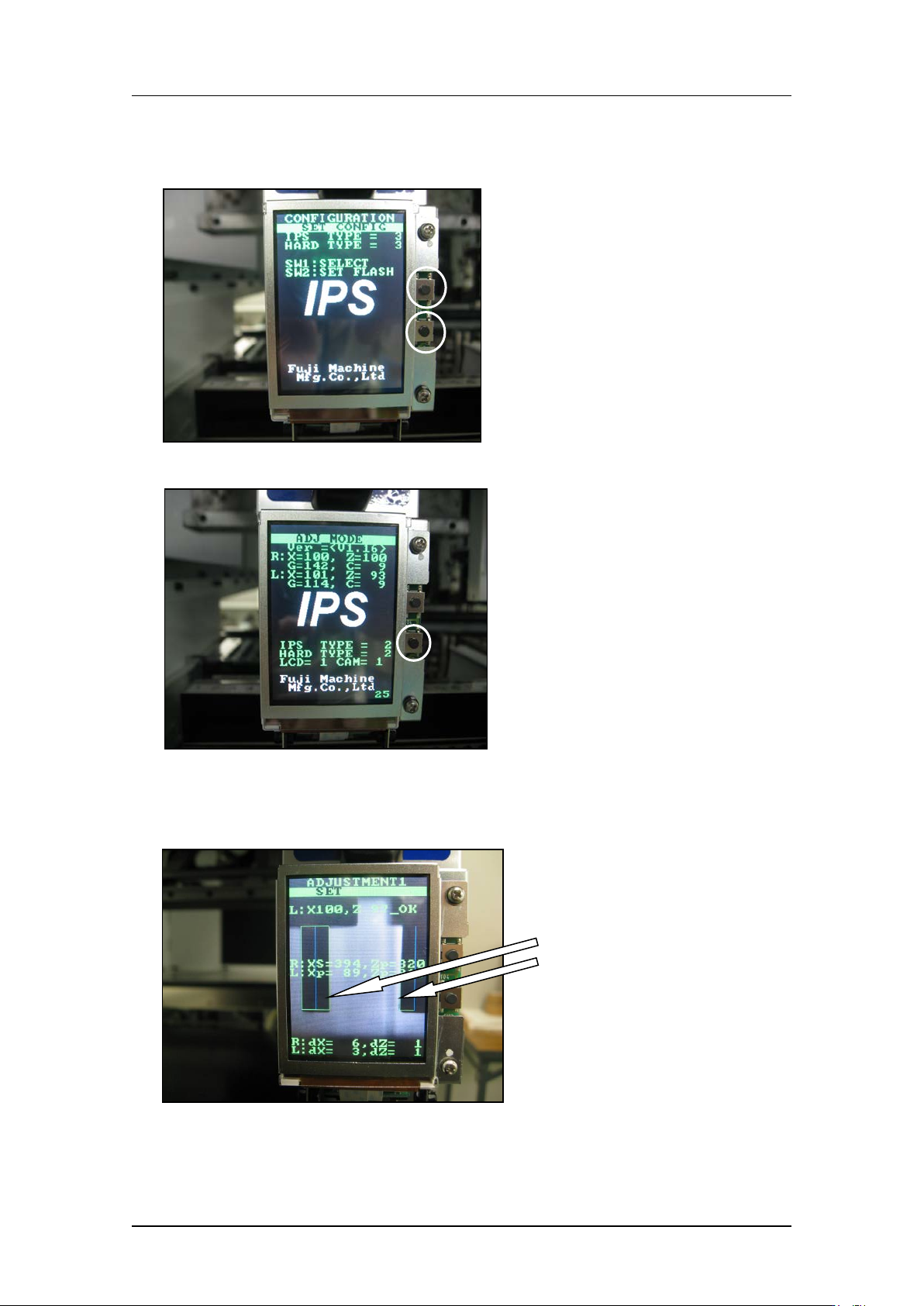
1. Press the upper and lower buttons s i m ultaneously t o retur n t o “ADJ MODE”.
2. Press the low er but t on t o enter “ ADJ USTM E NT 1” mode.
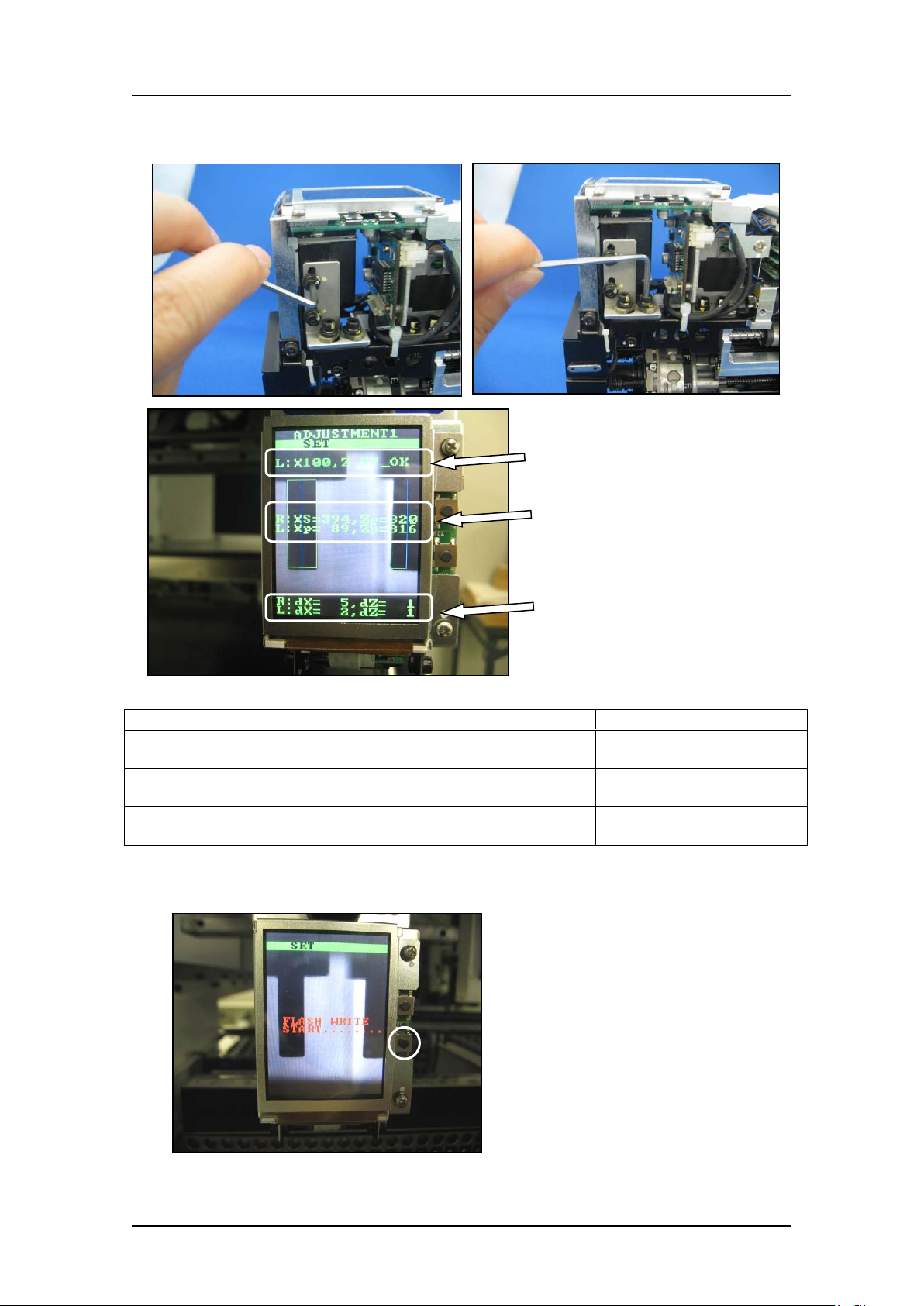
3. Use MotionTool.mini to check that the A holder is at the front of the head (the position
where the B and L holders are aligned).With holder A at this position, adjust the
position of the camera so that the jigs on the B and L holders match up with the green
frames on the scre en.
The jigs match the
green frames on the
screen.
CONFIDENTIAL
Edition 1.0 IPS Adjustment for Various Head Types on the Module
<V12 head>
FK-9F50-74-0E
4-9
FUJI CORPORATION
4. Use the bolts below to adjust the camera position so that the center value, resolution
and tilt are al l w ithin t olerance.
Inspection item
Tolerance
Target value
Camera resolution
L: X = 90~110
L: Z = 90~110
Same as tolerance
Center val ue
R: Xs = 380~400, Zp = 310~330
L: Xp = 80~100, Zp = 310 ~330
R: Xs = 390, Zp = 320
L: Xp = 90, Zp = 320
Tilt
R: dX = 0~9, dZ = 0~9
L: dX = 0~9, dZ = 0~9
R: dX = 0, dZ = 0
L: dX = 0, dZ = 0
5. Press the lower button to save the settings, and then press the upper button to enter
[ADJUSTM ENT 2 ] mode.
Resolution
Center val ue
Tilt
CONFIDENTIAL