IPS adjustment on the modules.pdf - 第90页
Edition 1 .0 IPS Adjustment for V arious H ead T ypes on the Module <V12 h ead> FK - 9F50 -74-0E 4- 14 FUJI CORPORA TION Checki ng t he fi e l d of vision ( ADJUSTMENT3) External l ight ca n af fect th e result s, …
Edition 1.0 IPS Adjustment for Various Head Types on the Module
<V12 head>
FK-9F50-74-0E
4-13
FUJI CORPORATION
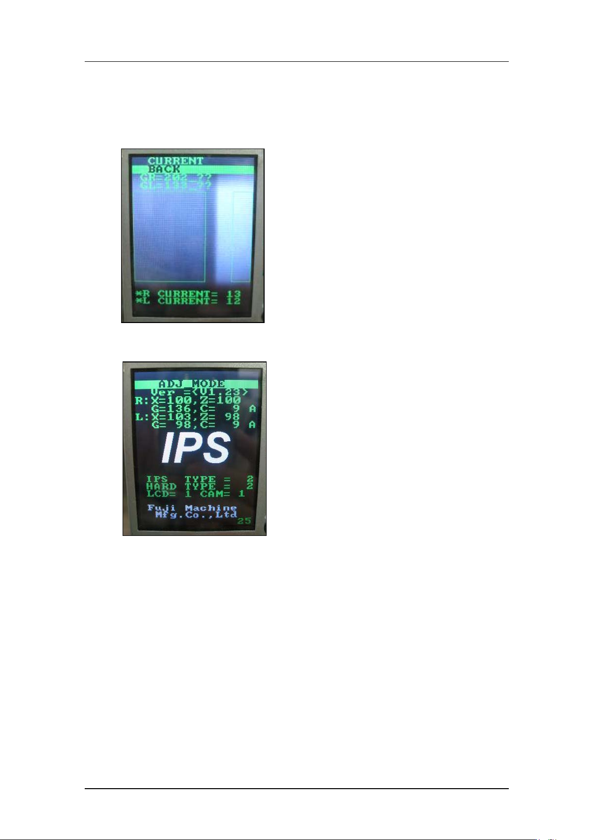
4. Press and hold the lower but ton for 2 to 3 seconds. An asterisk mark * d isplays next
to both the R CURRENT and L CURRENT values. The l ower button can now be
used to adjust t he R CUR RE NT and L CURRENT values toget her. O nce the values
are within to lerance, press t he upper button once with [BACK] selected to r et ur n t o
the [CURRENT] screen. Pr ess t he upper butt on once to select [S ET] and then
press the low er but ton once to save the v alues.
5. Use the upper but t on t o r eturn to [ADJ MODE] and t hen r eboot the m achine to t ur n
the head pow er O FF and return to [AUTO MODE].
CONFIDENTIAL
Edition 1.0 IPS Adjustment for Various Head Types on the Module
<V12 head>
FK-9F50-74-0E
4-14
FUJI CORPORATION
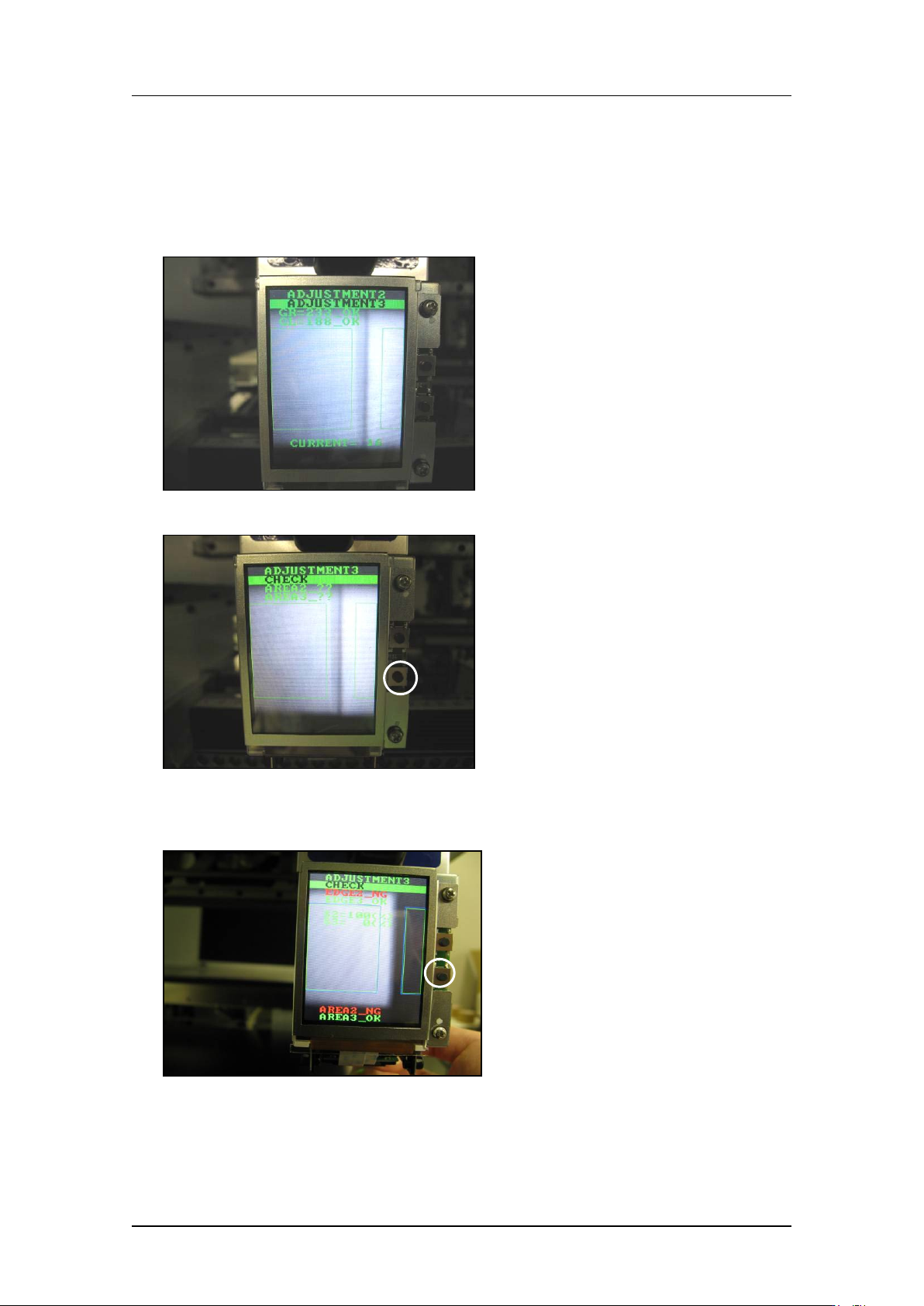
Checki ng t he fi e ld of vision (ADJUSTMENT3)
External l ight can affect the results, so be sure t o perform the pr ocedure in a shaded area.
1. Continuing from the procedure above, press the upper button to display
“ADJUSTMENT 2 ADJUSTMENT 3”.
2. Press the low er but t on t o display “ A DJUSTMEN T 3 CHECK”.
3. Block one of the glasses with some paper etc., and then press the lower button. (In the
example below, the right-hand glass as viewed from the front of the machine is
blocked).
CONFIDENTIAL
Edition 1.0 IPS Adjustment for Various Head Types on the Module
<V12 head>
FK-9F50-74-0E
4-15
FUJI CORPORATION
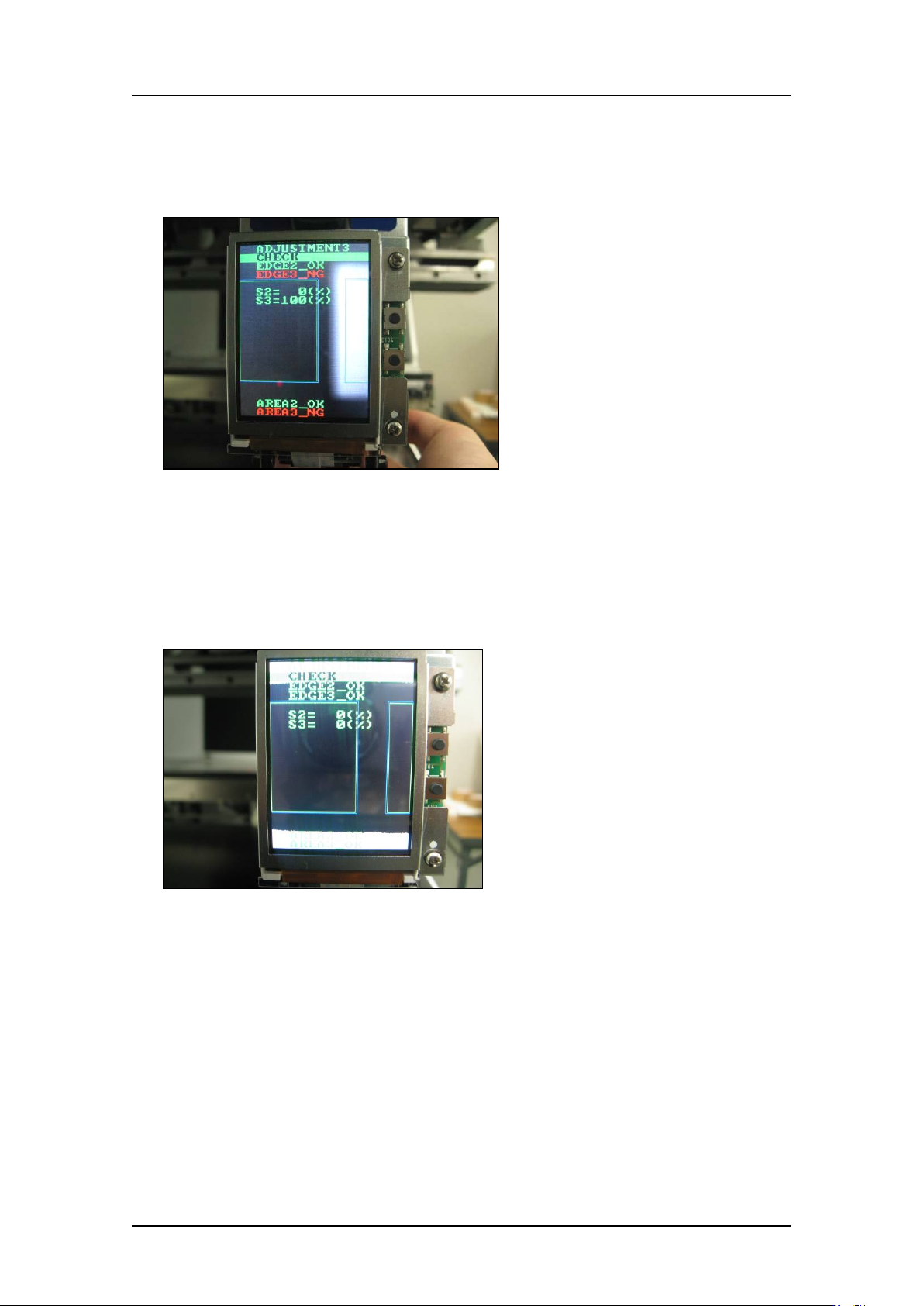
4. Check that “EDGE2_NG, EDGE3_OK” displ ays. A lso che ck t hat S2 = 100 %, S3 = 0 %
displays.
5. 4. Block the other glass with some paper and then press the lower button. (In the
example b elow t he left-hand gl ass as viewed from the fro nt of the machine is blocked).
6. Check that “EDGE2_OK, EDGE3_NG” displays. Also, check that S2 = 0 %, S3 =
100 % displays.
7. Press the upper and lower buttons simultaneously to reverse the LCD contrast, and
then check that there are no white areas within the green rectangles. If there are white
areas within the green rectangles, it is necessary to readjust the position of the camera.
If the camera position is readjusted, it is necessary to check the resolution, center
values and t ilt.
CONFIDENTIAL