IPS adjustment on the modules.pdf - 第98页
Edition 1 .0 IP S Adjustment for V ariou s Head T ypes on the Module < H12HS Q h ead > FK - 9F50 - 74 -0 E 5-2 FUJI CORPORA TION 2. Attach t he jigs to holder s B and L on the head ( AA63T0* ) and then attach th e …
Edition 1.0
IP S Adjustment for V arious Head Types on the Module
< H12HSQ head>
FK-9F50-74-0E
5-1
FUJI CORPORATION
Chapter 5- H12HSQ IPS adjustment
Camera position adjustment, current value (grayscale value)
adjustment, and area check
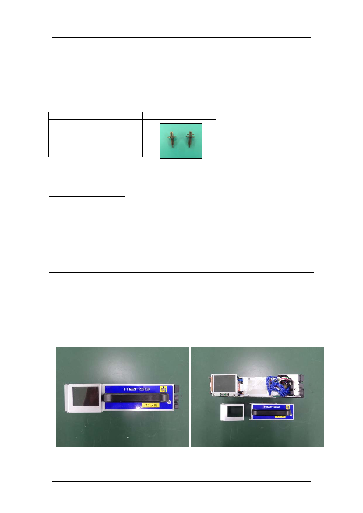
Required jigs
Drawing No.
QTY
Photo
2AGKHJ0132**
(New drawing No.)
AA63T0**
(Old drawi ng N o.)
2
Required software
Name
MotionTool.mini
Motion Adjustment T ool
Inspection item
Tolerance
LED current adjust m ent
Adjust the current value so that GR = 95 or above and G L = 9 5
or above (GR and GL
grayscale values should be in the
range 95~250. Target is 120).
CURRENT = 24 mA or less
Camera resolution ch eck
L: X = 92~108
L: Z = 92~108
Center val ue
R: Xs = 380~400 (Target: 390), Zp = 310~330 (Target: 320)
L: Xp = 80~100
(Target: 90), Zp = 310~3 30 ( Target: 320)
Tilt
R: dX = 0~9 (Target: 0), dZ = 0~9 (Target: 0)
L: dX = 0~9
(Target: 0), dZ = 0~9 (Target: 0)
Preparation on the module
1 Remov e t he covers
CONFIDENTIAL
Edition 1.0
IP S Adjustment for V arious Head Types on the Module
< H12HSQ head>
FK-9F50-74-0E
5-2
FUJI CORPORATION
2. Attach the jigs to holders B and L on the head (AA63T0*) and then attach the head to
the module.
To adjust the IPS camera position, it is necessary to move the head R-axis to the
holder A calibratio n data position.
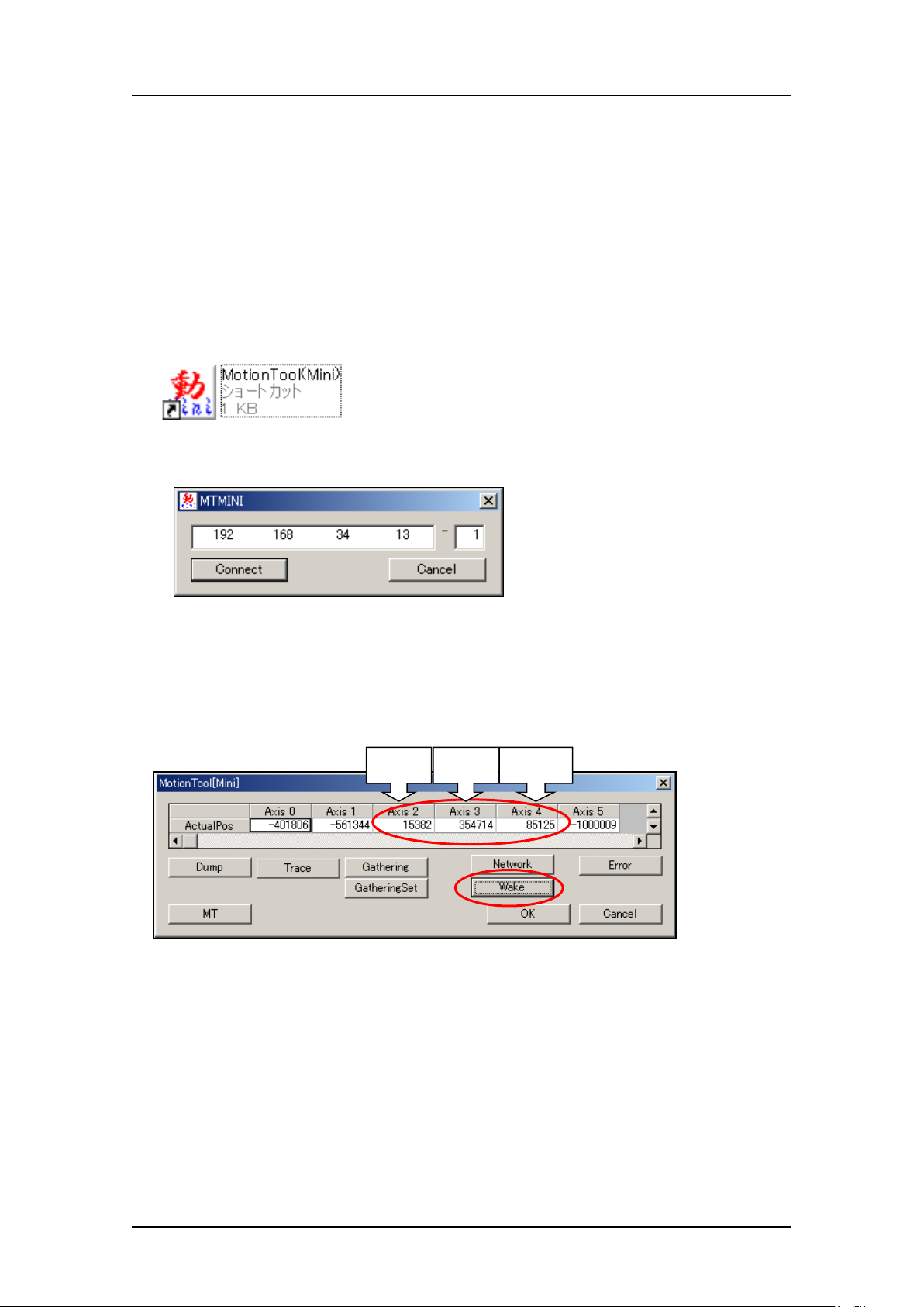
The follow ing st eps explain how t o check the servo counter using MotionTool(Min i).
3. After the machine wakes up, press [Start] button and then press [Cycle stop] button
immediately. At that time, ma ke sur e t he holder A has been moved to the front.
4. Startup MotionTool(Mini).
5. Enter the IP addre ss of the base and t he module number, and then click [Connect].
6. Select [Wake] - [Automatic recognition] - [OK] to start up the servo. After about 10
seconds, t he cur r ent s er vo count for each axis w ill be dis played.
7. The Axis 3 is the R-axis s er vo counter. Record this v alue. ( Re ference valu e: 0 to 60, 000
pulses) Keep this posit io n to adjust the IPS camer a position.
Z-axis
R-axis
Q-axis
CONFIDENTIAL
Edition 1.0
IP S Adjustment for V arious Head Types on the Module
< H12HSQ head>
FK-9F50-74-0E
5-3
FUJI CORPORATION
The following steps ex plain how t o c heck the servo counter us ing Motion Adjustment Tool.
8. After the machine wakes up, press [Start] button and then press [Cycle stop] button
immediately.
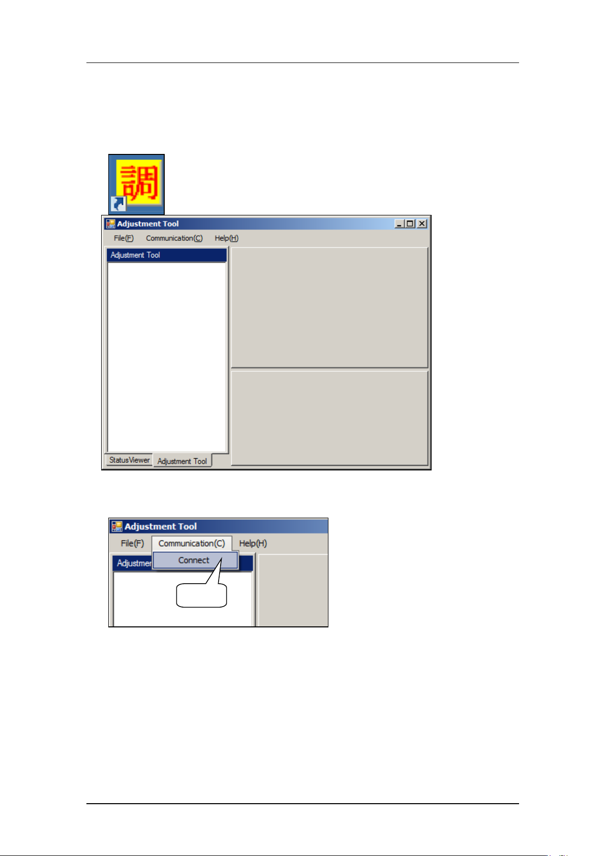
9. Start up Moti on Adjustment Tool.
10. Select [Comm unication] – [Connect].
Select
CONFIDENTIAL