YSM20_YSM20W_Mainte_E.pdf - 第114页
3-56 3 Periodic maintenance items t Spread the grease. 1. Close the machine safety cover and cancel the emergency stop. Attach the carriage if the machine is the carriage type. 2. Change the conveyor width to maximum and…
3-55
3
Periodic maintenance items
0
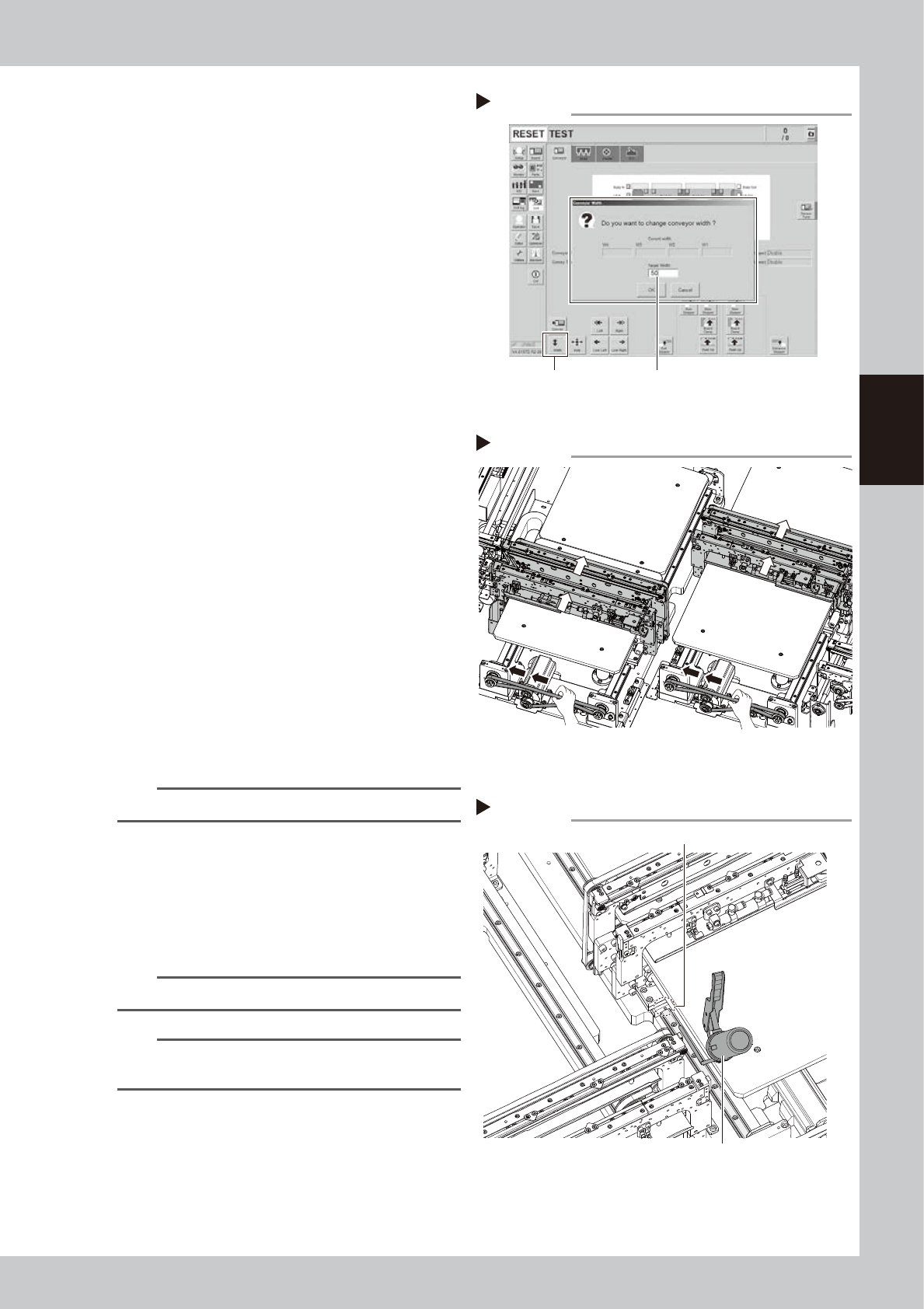
Change the conveyor width to the
minimum width.
1. Close the machine safety cover and
cancel the emergency stop. Attach the
carriage if the machine is the carriage
type.
2. Press the [Width] button to display the
"Conveyor Width" screen.
3. Enter the minimum value of the conveyor
width "50 mm" in the "Target Width" box
and press the [OK] button. The conveyor
width is changed to the specified width.
q
Raise the push-up unit.
Raise the push-up unit following Step 3.
e
w
Apply grease to rest of ball screw
and hexagon spline.
1. Press the emergency stop button and
then open the machine safety cover.
2. If the machine is carriage type, detach
carriage to access to the conveyor.
3. Apply the specified grease (NSL) with
finger uniformly over the hexagon spline
shaft surface and ball screw surface and
groove where grease could not be
applied in Step 8.
e
Move the conveyor U axes.
Each U-axis can be moved by moving the
belt in front of W2-axis (U1-axis) and W3-axis
(U2-axis) manually.
Move the belt to the black arrows' directions
in the figure. Then Move the W2-axis (U1-axis)
and W3-axis (U2-axis) about 300 mm to the
white arrows' directions in the figure.
TIP
Move the belt slowly when moving it manually.
r
Apply grease to rest of guide.
Apply grease to the grease nipples that
grease could not be applied in Step 9.
Inject the specified grease (NSL) to the
grease nipple of the guide with a grease
gun (bent type nozzle).
n
NOTE
Apply grease until the new grease oozes from the gap.
n
NOTE
See "Chapter 5 Lubrication points" for the position and
quantity of grease nipples of the guide.
Changing conveyor width to minimum
Step 10
[Width] button Enter “50 mm”.
54320-N2-00
W2-axis (U1-axis)W3-axis (U2-axis)
Moving U axes
Step 13
533B4-N2-00
Applying grease to guide 2
Step 14
Grease nipple
Grease gun (30°-bent type)
533B5-N2-00

3-56
3
Periodic maintenance items
t
Spread the grease.
1. Close the machine safety cover and
cancel the emergency stop. Attach the
carriage if the machine is the carriage
type.
2. Change the conveyor width to maximum
and minimum several times referring to
Step 5 and Step 2.
n
NOTE
When changing the conveyor width, an error may
occur as the U-axis is moved manually in Step 13.
In this case, see "2.3.1 Checking the conveyor sensor
condition and operation" in this chapter to perform the
conveyor sensor tuning.
e
y
Wipe away excess grease.
1. Press the emergency stop button and
then open the machine safety cover.
2. If the machine is carriage type, detach
carriage to access to the conveyor.
3. Wipe away excess grease on the edge
of ball screw, guide, and hexagon spline
shaft with lint-free cloth.
3-57
3
Periodic maintenance items
5.3.2 YSM20/20W Dual-lane: Cleaning and lubricating W-axis
The following describes the cleaning and lubrication procedure of W-axis of YSM20/YSM20W dual-lane type.
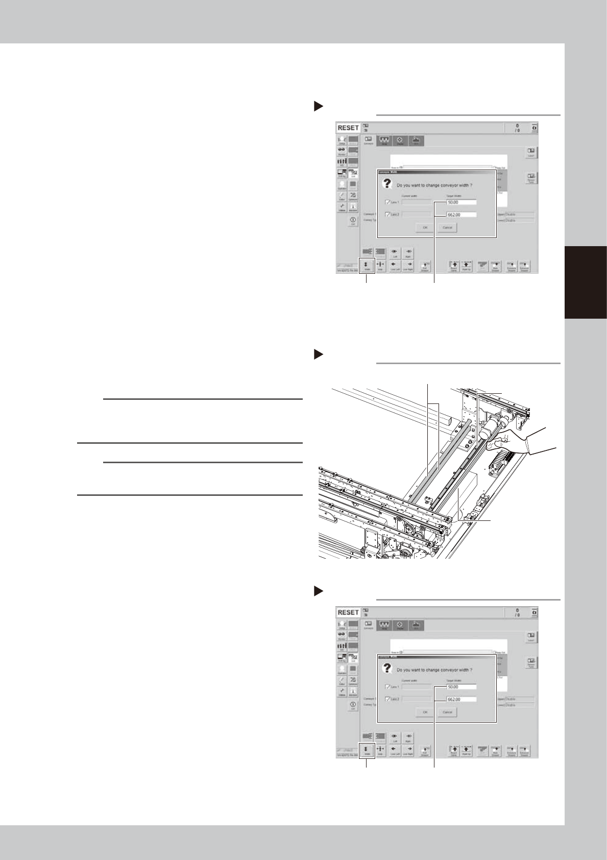
1
Move the conveyor forward.
1. Press the [Width] button to display the
"Conveyor Width" screen.
2. Enter "50 mm" in the "Target Width" box of
"Lane 1". Enter "410 mm" in the "Lane 2"
for YSM20. Enter "662 mm" in the "Lane 2"
for YSM20W . Pressing the [OK] button
changes the conveyor width to the
specified width.
e
2
Clean each part of W-axis.
1. Press the emergency stop button and
then open the machine safety cover.
2. If the machine is carriage type, detach
carriage to access to the conveyor.
3. Take off all accessories susceptible to the
magnetic fields, such as a wristwatch
and/or magnetic ID card.
4. Wipe the old grease and soiling on entire
areas of 4 ball screws, 2 guides , and 2
hexagon splines of the W-axis with
lint-free cloth.
n
NOTE
Carefully wipe the lead grooves of the ball screw and
guide rail during the cleaning. Additionally, make sure
that any dirt is not produced after wiping.
n
NOTE
See "Chapter 5 Lubrication points" for the positions and
quantities of ball screw, guide, and hexagon spline.
3
Move the conveyor width to the
lubrication points.
1. Close the machine safety cover and
cancel the emergency stop. Attach the
carriage if the machine is the carriage
type.
2. Press the [Width] button on the [Unit]
- [Conveyor] screen to display the
"Conveyor Width" screen.
3. Enter the following value in the "Target
Width" box.
YSM20:
Lane 1: 230 mm
Lane 2: 50 mm
YSM20W:
Lane 1: 300 mm
Lane 2: 150 mm
The conveyor width is changed to the
specified width by pressing the [OK]
button.
Moving conveyor forward
Step 1
[Width] button Enter following values.
Lane 1 : “50 mm”
Lane 2 : “410 mm” (YSM20)
“662 mm” (YSM20W)
54321-N2-00
Cleaning W-axis
Step 2
Ball screw
Guide
Hexagon spline
533B6-N2-00
Moving conveyor to lubrication point
Step 3
[Width] button Enter following values.
[YSM20 ] Lane 1 : “230 mm” / Lane 2 : “50 m”
[YSM20W ] Lane 1 : “300 mm” / Lane 2 : “150 m”
54322-N2-00