YSM20_YSM20W_Mainte_E.pdf - 第140页
Chapter 5 Lubrication points Contents 1. Lubrication preparations 5-1 1.1 Compatible grease 5-1 1.2 Grease gun 5-2 2 . Lubrication points/schedule (Main machine) 5 - 3 2.1 X-axis 5-3 2.2 Y -axis 5-4 2.3 W-axis (U-axis) 5…
4-6
4
Maintenance of options
5
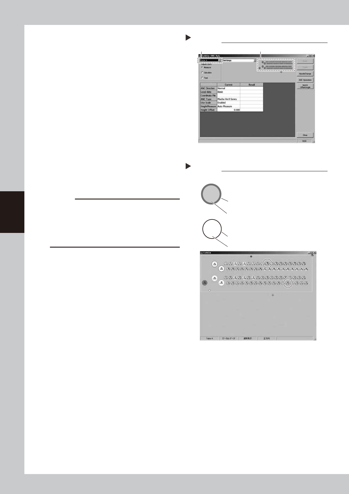
Open the ANC Auto screen.
1. Select a desired table from the pull-down
menu at the upper left of screen.
2. Click ANC figure on the right of screen.
6
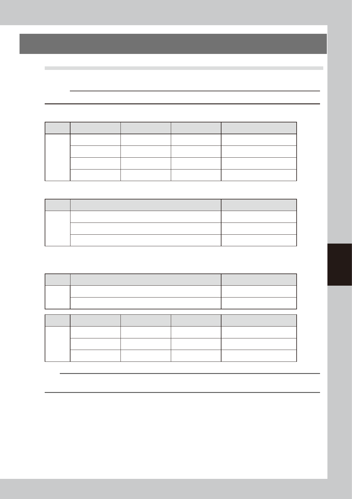
Check the ANC sensor operation.
1. Check that the nozzle storage status
shown on the screen is the same as the
actual nozzle storage status referring to
the nozzle storage position/sensor status
in the figure.
2. Remove the nozzle manually and check
that no nozzle is displayed at the target
storage position.
7
Clean the ANC.
If the nozzle detection status is different from
the actual nozzle presence status, remove
the nozzle and visually check the inside. If
any dust or chip is found, remove it and
clean the inside of the nozzle using the
vacuum assembly.
c
CAUTION
If the nozzle detection status inside the ANC does not
become stable for a reason other than clear reason,
such as dust, etc., or if the nozzle cannot be detected,
contact your distributor. The disassembly and cleaning
performed by the customer are not covered by the
warranty.
8
Close the ANC shutter.
Press the [Nozzle. Stn Shutter] button to close
the ANC shutter.
Opening the ANC Auto screen
Step 5
Select the table A or table B. Click the ANC figure.
54404-N2-00
2-303
10
7-SP
68
Checking the ANC sensor operation
Step 6
303 nozzle to be used for head 2
Storage position: No. 10
Colored frame (red/blue/yellow/green, etc.):
Nozzle is already registered.
Special nozzle to be used for head 7
Storage position: No. 68
Black frame: Nozzle is not registered.
Gray out: Nozzle is present currently.
White: Nozzle is not present currently.
Example of nozzle storage position/sensor status
54405-N2-00

Chapter 5 Lubrication points
Contents
1. Lubrication preparations 5-1
1.1 Compatible grease 5-1
1.2 Grease gun 5-2
2. Lubrication points/schedule (Main machine) 5-3
2.1 X-axis 5-3
2.2 Y-axis 5-4
2.3 W-axis (U-axis) 5-5
2.3.1 Dual-stage type 5-5
2.3.2 Dual-lane type 5-6
2.3.3 Single-lane type 5-7
2.4 PU-axis 5-8
2.4.1 Dual-stage type 5-8
2.4.2 Dual-lane type 5-9
2.4.3 Single-lane type 5-10
2.5 Head unit 5-11
2.5.1 HM head unit 5-11
2.5.2 FM head unit 5-12
5-1
5
Lubrication points
1. Lubrication preparations
1.1 Compatible grease
For greasing procedures, always use the YAMAHA prescribed grease shown below.
c
CAUTION
Using unauthorized grease could damage the machine.
n
Main unit
Lubrication Point Guide Ball screw Remarks
Main
unit
X-axis NSL grease NSL grease
Y-axis NSL grease ― Guide only
W-axis (U-axis) NSL grease NSL grease Also used at hexagon spline
PU-axis ― NSL grease
n
Head unit
Lubrication Point Grease
FM head
unit
Ball screw NSL grease
Guide AFF grease
Spline shaft LRL grease
n
Option
Lubrication Point Grease
Feeder
exchange
carriage
Positioning section NSL grease
Guide rail cover clamp section (ZS feeder carriage only) NSL grease
Lubrication Point Guide Ball screw Remarks
cATS10
sATS30
AZ-axis
NSL grease NSL grease
AH-axis
NSL grease NSL grease
AT-axis
NSL grease NSL grease
n
NOTE
For details about how to apply the grease to the cATS10, sATS30, and feeder exchange carriage, see the "Z:LEX Option
Manual".