YSM20_YSM20W_Mainte_E.pdf - 第178页
Inspection Check Sheet Serial No. This inspection check sheet describes from daily to monthly inspections. Copy this page and use it for inspection. Detail inspection procedures and inspections of 2-month interval or mor…
A-4
Appendix
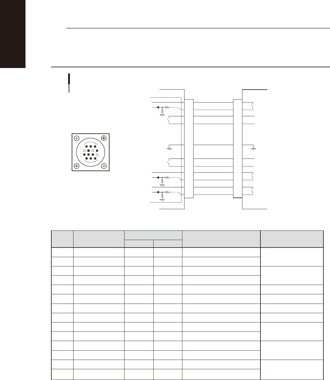
1.3.2 NEXT INTERFACE connector
When the following three conditions are met, the NEXT INTERFACE circuit in the machine allows the board to
be carried out.
1. Machine is ready for carrying in a board ((
Lane 1 BA OUT [T0100031] : ON / Lane 2 BA OUT [T0100033] : ON
)
2. Board carry-in signal is input from the upstream machine. ((
Lane 1
BUSY IN [N0100410] : ON /
Lane
2 BUSY IN [N0100413] : ON
)
3. Automatic operation signal is input from the upstream machine. ((
Lane 1
LR IN [N0100411] : ON /
Lane
2 LR IN [N0100414] : ON
)
n
NOTE
• When the automatic operation signal (LR IN) from the downstream machine turns off during transfer of a board,
the machine stops temporarily carrying out the PC.
• When the board being carried out is detected by the exit sensor, the BA OUT signal turns off.
• Carrying out the board is finished when both the BUSY IN and BA OUT turn off.
• The addresses of the lane 2 are used for the machines with the dual-lane specifications.
1
2
3
4
5
6
7
8
9
10
11
12
13
14
14
11
12
7
4
8
3
1
NEXT INTERFACE circuit
NEXT INTERFACE
connector
This machine NEXT INTERFACE Downstream machine
AMP 206043-1
(14-pin receptacle)
BUSY IN
(LANE 1:N0100410)
(LANE 2:N0100413)
+24V
+24V
UR OUT
(LANE 1:T0100030)
(LANE 2:T0100032)
LR IN
(LANE 1:N0100411)
(LANE 2:N0100414)
+24V
LE IN
(LANE 1:N0100412)
(LANE 2:N0100415)
BA OUT
(LANE 1:T0100031)
(LANE 2:T0100033)
Signal output during board
carry-in
Signal input to request board
carry-out
Signal input during automatic
operation
Signal output during automatic
operation
Signal output during waiting
for board between machines
I/O BOARD
GND GND
53A05-N2-00
n
Board transfer signal specifications (NEXT INTERFACE)
Pin No. Signal name
Address
I/O specifications Signal specifications
LANE 1 LANE 2
*1
1 +24V Input common (+24V)
Signal input during board
carry-in
2 BUSY IN N0100410 N0100413 Voltage input
3 BA OUT T0100031 T0100033 Relay contact (zero voltage) output
Signal output to request
board carry-out
4 BA OUT T0100031 T0100033 Relay contact (zero voltage) output
5 NC
6 NC (with dummy pins) (Prevents misinsertion.)
7 GND
8 NC
9 UR OUT T0100030 T0100032 Relay contact (zero voltage) output
Signal output during
automatic operation
10 UR OUT T0100030 T0100032 Relay contact (zero voltage) output
11 +24V Input common (+24V)
Signal input during
automatic operation
12 LR IN N0100411 N0100414 Voltage input
13 +24V Input common (+24V)
Signal input during
waiting for board between
machines
14 LE IN N0100412 N0100415 Voltage input
*1 Used for the machines with the dual-lane specifications.
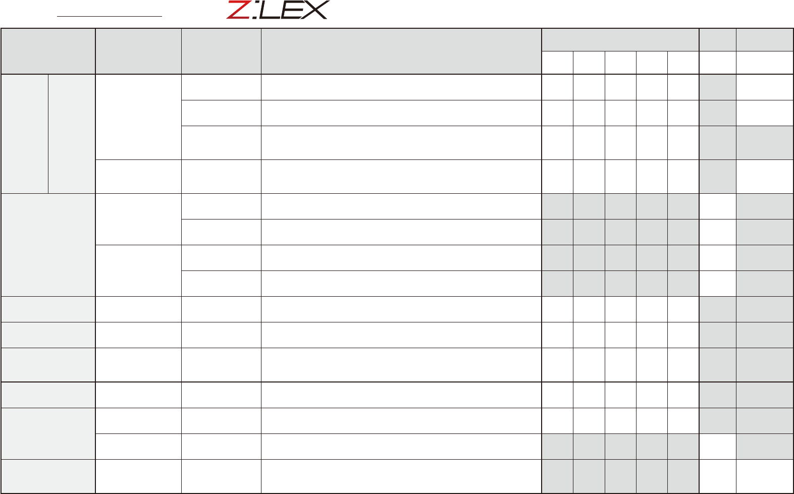
Inspection Check Sheet
Serial No.
This inspection check sheet describes from daily to monthly inspections.
Copy this page and use it for inspection.
Detail inspection procedures and inspections of 2-month interval or more
are described in each chapter of this manual.
Section Unit name Check items Inspection/work
Weekly (Mo./Day)
Monthly
Repair/
replacement
/ / / / / /
/
Head
units
HM/FM
Nozzle
Nozzle tip
Check nozzle tip visually. If not clean, remove dirt on component pickup
surface (nozzle tip) with nozzle tip cleaning tape that comes with machine.
Spring action
Press nozzle tip with finger to check the spring action. If not smooth,
disassemble and clean the nozzle and then apply grease.
Air path
Clean nozzle air path if vacuum level when nozzle is open is out of standard
value or once every month. Use air blow tool, nozzle cleaning wire or similar
tool.
Leaf spring
(Roller lock)
Nozzle mounting
status
Detach/attach nozzle manually to check that leaf spring (roller lock) has
enough griping force. Check that leaf spring is deformed or worn out. If it is
defective, replace it with new one.
X and Y axes
X-axis
Ball screw
Clean ball screw with dry cloth. After that, apply specified grease (NSL) with
grease gun. Operate ball screw to spread the grease.
Guide
Clean guide with dry cloth. After that, apply specified grease (NSL) with grease
gun. Operate guide to spread the grease.
Y-axis
Guide
Clean guide with dry cloth. After that, apply specified grease (NSL) with grease
gun. Operate guide to spread the grease
Linear scale
Check that old grease remains on linear scale. If so, clean the linear scale
referring to the cleaning procedure (described in Chapter 3 2.2.1).
Conveyor
Board sensor Sensor status
Clean sensor section if dirt or dust is found. Check that the sensor works
correctly even after changing the conveyor width.
Recognition unit
Multi-camera Protective glass
Clean light protective glass of multi-camera if dirt or dust is found. If extremely
dirty, wipe off dirt with dry cloth or cloth with a small amount of lens cleaner.
Tape cutter
Tape cutter
Tape cutter sharpness
Abnormal sound
Check that abnormal sound is not heard when cutting tape.
Check that tapes in empty tape box are cut correctly.
*Contact YAMAHA sales representatives when abnormality is noticed.
Feeder bank
(Fixed feeder bank)
Feeder plate Plate
Check feeder plate surface visually. If dirt or dust is found, clean with home
vacuum cleaner (or vacuum assembly).
Feeder exchange
carriage
Feeder plate
*1
Plate
Clamp unit
Check feeder plate and clamp unit area visually. If dirt or dust is found, clean
with home vacuum cleaner (or vacuum assembly).
Positioning section
*1
Positioning pins
Wipe off old grease on positioning pins inserted in feeder exchange carriage
and machine. Then apply grease (NSL) with cotton swab or similar tool.
Ionizer
(Machine option)
Discharge needle
Cleaning discharge
needle tip
Stop supplying main air. Then clean discharge needle tip using cotton swab
with ethanol. After that, leave discharge needle for a while until it dries. If an
error still occurs even after cleaning, replace it with new one.
*1
See "Z:LEX Option Manual" for how to maintain feeder exchange carriage and tray changer.

Version 5.10
Maintenance Manual September 2020