TR7500_Series_Software_v29_En - 第112页
Test Research Inc. 90 TR7500 Series User Guide – Software v.2.9.0 Figure 152 : Procedure to A dd Componen t in Project 2. Move selecting tools to t he obj ect componen t center. The component has to be on board 1. 3. Inp…
Test Research Inc.
TR7500 Series User Guide –Software v.2.9.0 89
3.7 Procedure: Add Component in Project
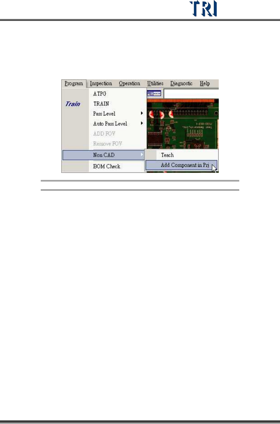
This is to add a new component to an existing project with non-CAD function.
Figure 151: Add Component in Project
1. Press [P
ROGRAM
>
N
ON
CAD
>
A
DD
C
OMPONENT IN PROJECT
.] and enter the dialog
as in the following figure.
Test Research Inc.
90 TR7500 Series User Guide –Software v.2.9.0
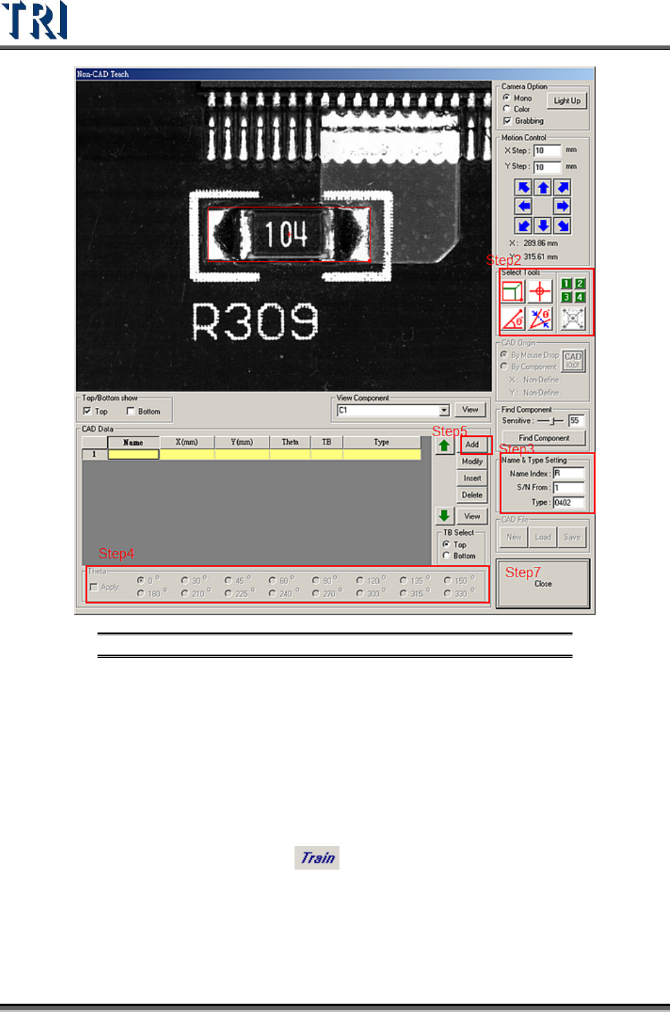
Figure 152: Procedure to Add Component in Project
2. Move selecting tools to the object component center. The component has to be
on board 1.
3. Input data at [Name &Type Setting] field
4. Check [Apply] and select an angle.
5. Press [CAD Data/Add] to create the component data.
6. Add the other components on board 1.
7. Press [Close] to exit.
8. Press [P
ROGRAM
>
T
RAIN
] or [ ] to enter the train dialog.
9. Use [Merge] button to merge the component library.
10. Press [U
TILITIES
>
C
APTURE
FOV
I
MAGES
] to get the FOV images again.
Test Research Inc.
TR7500 Series User Guide –Software v.2.9.0 91
3.8 Inspection Tab
Figure 153: Inspection Tab
3.8.1 Inspect Panel
Start to inspect the PCB with standard procedure.
3.8.2 Debug for Single Board Set
Start to inspect, but it shows only the result of one set.
3.8.3 Inspect FOV Images
Inspect the FOV images that are saved in hard disk.
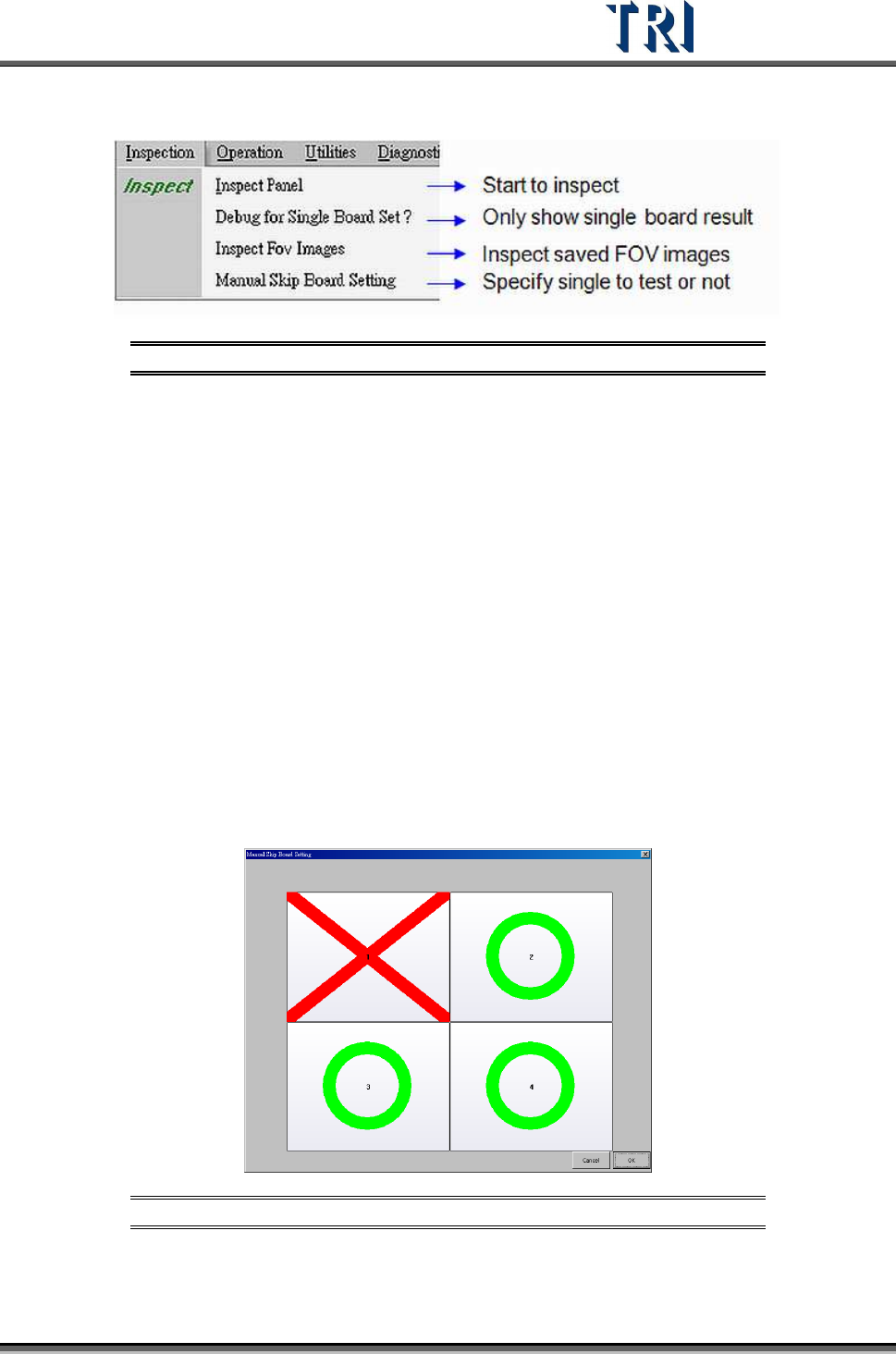
3.8.4 Manual Skip Board Setting
Use this function to specify whether each board is to be tested or not.
As per the image below, click on the board directly. The green O means that the single board
has to be inspected and the red X means that the single board does not have to be inspected.
Then press [OK] to finish setting.
Figure 154: Manual Skip Board Setting Window