TR7500_Series_Software_v29_En - 第127页
Test Research Inc. TR7500 Series User Guide – Software v.2.9.0 105 Figure 172 : Confirm Static or Board In/Out Test 3.10.12 Resend Image Data for Repair This function is enabled when [Parameter/User Mode/Link to Repa ir …
Test Research Inc.
104 TR7500 Series User Guide –Software v.2.9.0
Formula
i
X=
Result
n
=
countTest
n
X
∑
==
i
X
Average
1
)(
Sigma
2
−
−
==
∑
n
XX
i
σ
−−
=
σσ
3
)(
,
3
)( LSLXXUSL
MinC
pk
USL and LSL present the upper spec limit and lower spec limit. Set the value when
starting this function.
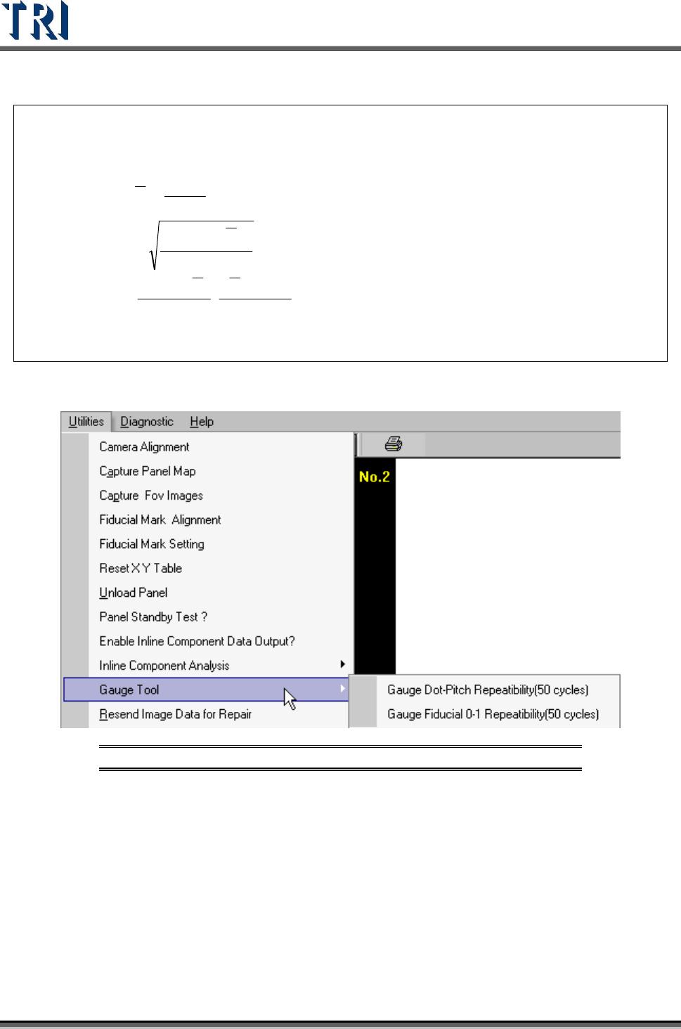
3.10.11 Gauge Tool
Figure 171: Utilities Tab -- Gauge Tool Options
3.10.11.1 Gauge Fiducial 0-1 Repeatability (50 cycles)
System will measure the distance between two fiducial marks for 50 times and output the
result in [C:\AOI] folder. The first measurement file name is [fireport1.txt] and the next files
will be [fireport2.txt], [fireport3.txt] and so on. Select YES for static or NO for board in and out
test.
Test Research Inc.
TR7500 Series User Guide –Software v.2.9.0 105
Figure 172: Confirm Static or Board In/Out Test
3.10.12 Resend Image Data for Repair
This function is enabled when [Parameter/User Mode/Link to Repair Station] is selected.
Press the item and the system will send the data to repair station (Including *dir.1, *.win,
*.img, *.bmp).
3.10.13 Enable Inspection Data Collection
Select this item to save the result for all components as a text file. The file will be saved in
the folder that the project is saved in and the file name is “Year-Month-Date-Time”.
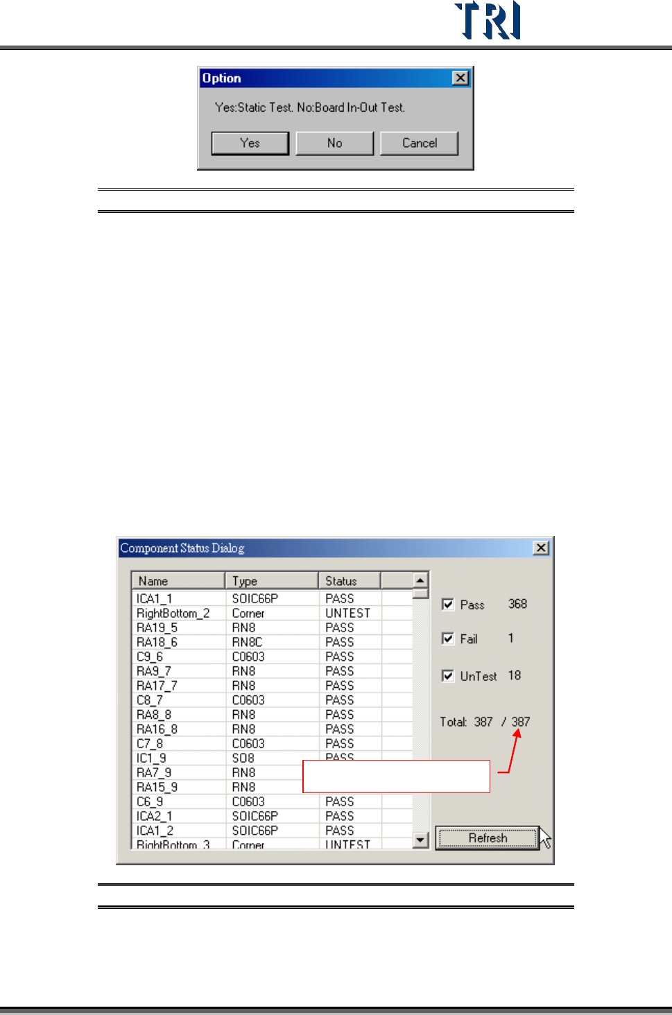
3.10.14 Component Status
This can only be selected in the [Train] dialog.
After selecting [Pass], [Fail] and [Untest], press [Refresh]. The system will display the number
of components which are passed, failed or untest.
Number of components
Figure 173: Component Status Dialog
3.10.15 Generate Real Image Data
Generate the image to ICT or ATE machine.
Test Research Inc.
106 TR7500 Series User Guide –Software v.2.9.0
3.10.16 Inline Component Data Output to SPC
Output the [Cpk Data Collection] to SPC system. The output path is the same as the path
specified in [P
ARAMETER
>
P
ANEL
>
R
EPAIR
S
TATION
]..
After loading a .PRE file, save the .PRE file again to output the specification file. The name of
the file is the model name and its file name extension is .LSU. A .PRE file only has to be
saved once after the project is finished. If there is a new project created or a project is
modified, the system will send the LSU file automatically.
After inspecting a panel, the system sends a PFL file to the specified drive..
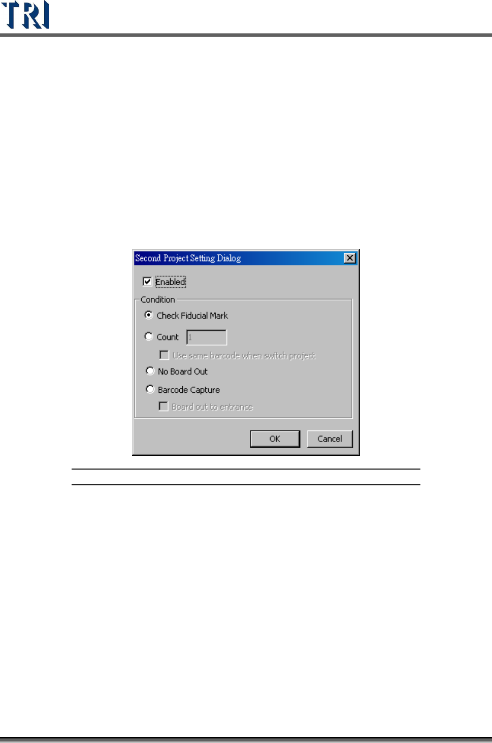
3.10.17 Second Project
Select two projects to be open in turn automatically.
Figure 174: Second Project Data Setting Dialog
[Enabled] – Check to start the function. Load two projects at the same time and the
system will change the project to inspect according to the conditions.
[Check Fiducial Mark] – When the system can’t find a fiducial mark it will change to
use the second project.
[Count] – Select and input number. After the first project is inspected for the
specified number of times, it will change to use second project. When set to “1”, the
barcode will remain the same for the second program.
[No Board Out] – After a board is sent into the machine, it will be inspected by the
first then the second project in sequence, then the board is sent to exit.
[Barcode Capture] – Change programs according to the type of barcode (software
or hardware barcode). If both fail, the board will be sent back to the start position.
If this function is selected, the two programs must have different barcode
types: one hardware and one software.