TR7500_Series_Software_v29_En - 第163页
Test Research Inc. TR7500 Series User Guide – Software v.2.9.0 141 5.9 Chang e to CCW (Counterc lockwi se) The default rotate direc t ion used by the TR7500 system is counte rclockwise (CC W ). If the definition of an gl…
Test Research Inc.
140 TR7500 Series User Guide –Software v.2.9.0
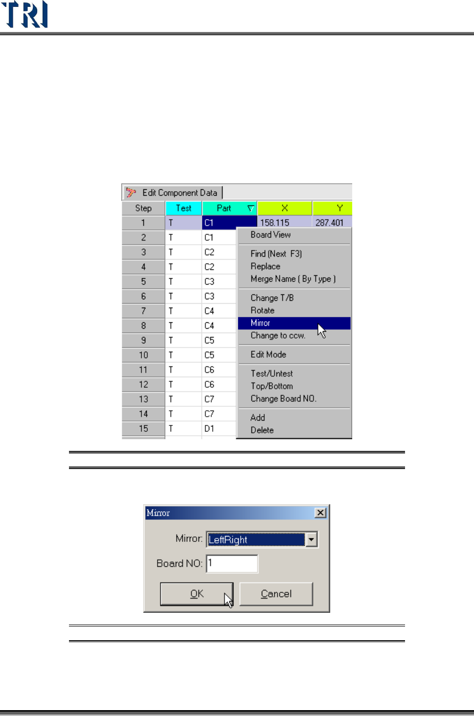
5.8 Mirror
Set the board mapping way from [LeftRight] or [TopBottom].
[LeftRight] – Change the board’s left side mapping to right side and right side
mapping to left.
[TopBottom] – Change the board’s top side mapping to the bottom and the
bottom side mapping to top.
Figure 227: Select Mirror Command
Select [LeftRight] or [TopBottom] way to mirror. Then select the board number to be mirrored.
Figure 228: Mirror Dialog
After mirroring, the system will change top side to bottom side and bottom side to top side
automatically. The [Change T/B] command can also be used if needed.
Test Research Inc.
TR7500 Series User Guide –Software v.2.9.0 141
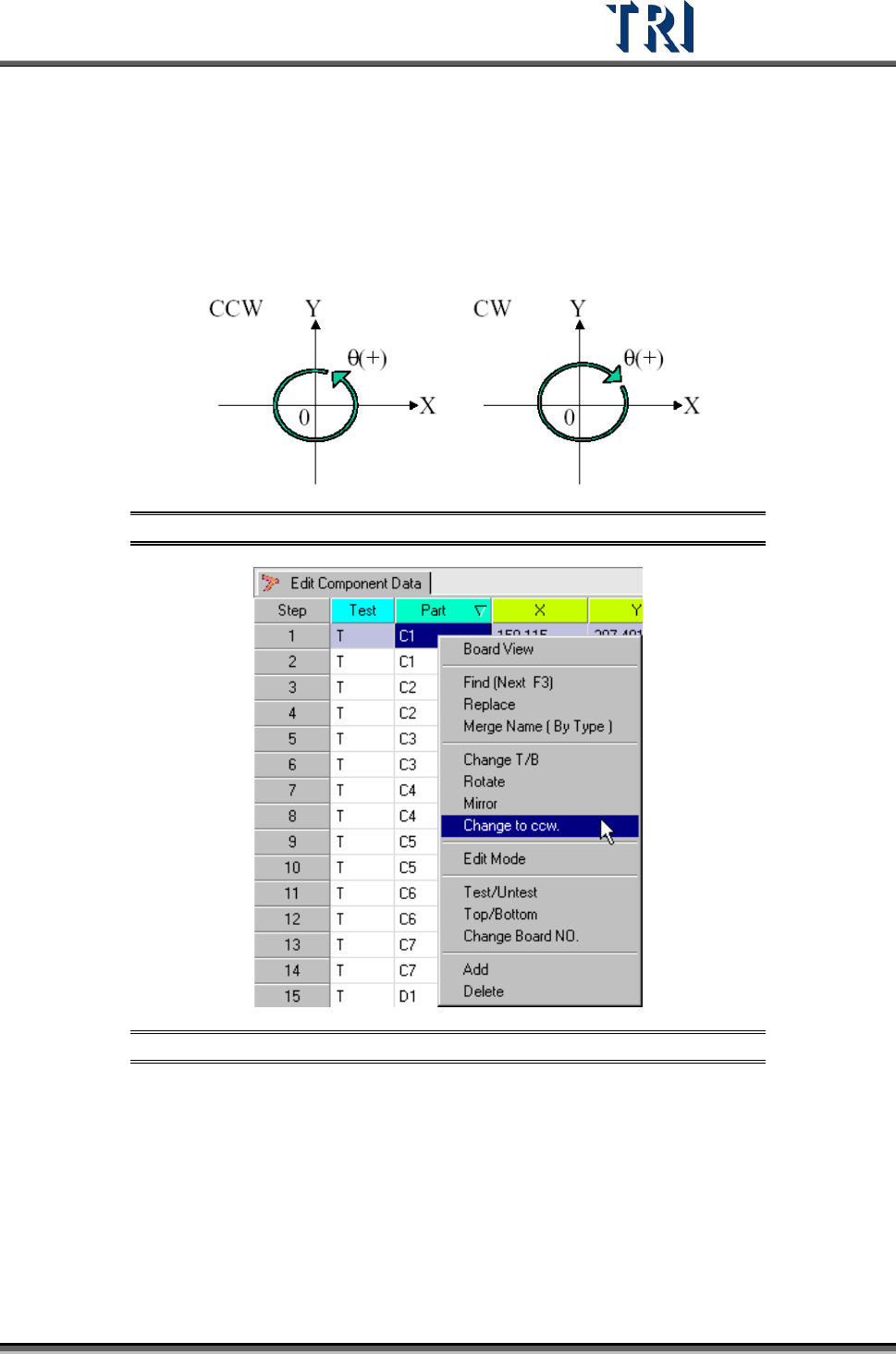
5.9 Change to CCW (Counterclockwise)
The default rotate direction used by the TR7500 system is counterclockwise (CCW). If the
definition of angles in the original CAD is clockwise (CW), the directions must be changed by
using this function.
Figure 229: Counterclockwise & Clockwise Rotation
Figure 230: Select Change to CCW Command
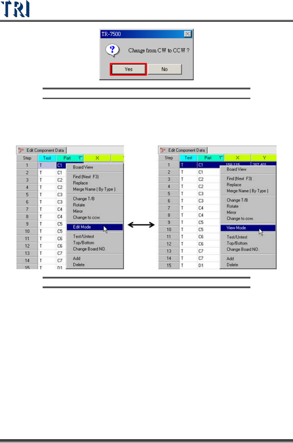
Display the double confirm message window.
Test Research Inc.
142 TR7500 Series User Guide –Software v.2.9.0
Figure 231: Change to CCW Confirm Window
5.10 Edit/View Mode
Change the [Component Data] table from [View] mode to [Edit] mode. The information of
components can be changed except [Test], [Part], [T/B] or [Board NO].
Figure 232: Select Edit/View Command
Click the [View Mode] and return to the view mode so that the data is not changed.