TR7500_Series_Software_v29_En - 第167页
Test Research Inc. TR7500 Series User Guide – Software v.2.9.0 145 5.13 Change B oard N o. (Numbe r) Assign speci fic components to a speci f ic board. General ly multi-board infor mation is created by the [Generate M ul…
Test Research Inc.
144 TR7500 Series User Guide –Software v.2.9.0
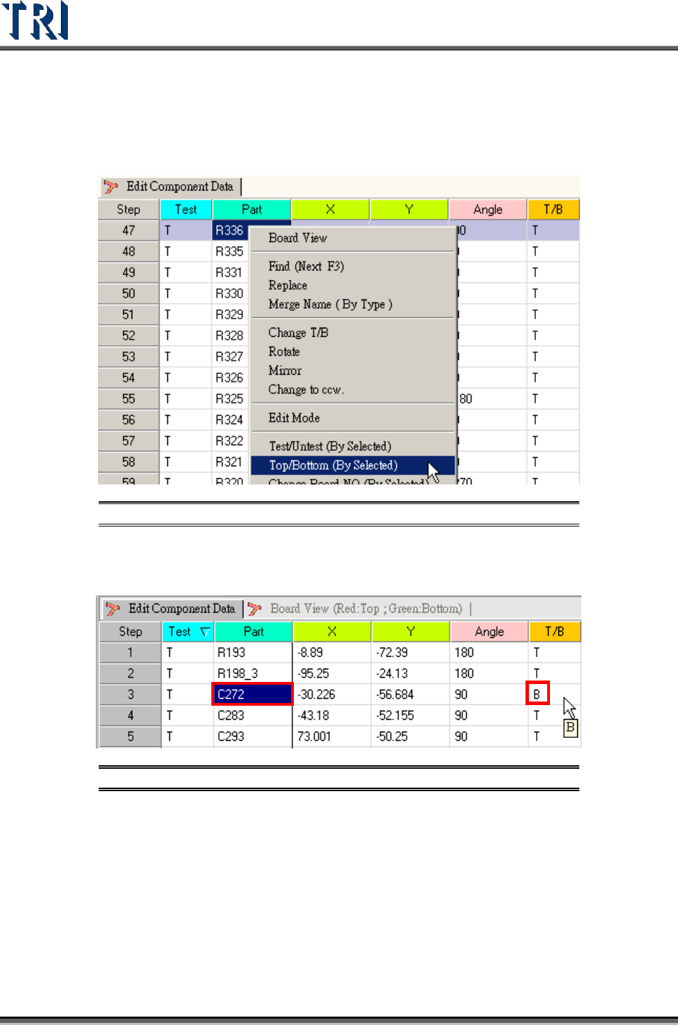
5.12 Top/Bottom
Change the specified components from top side to bottom side or bottom side to top side.
Figure 235: Select Top/Bottom Command
Display whether a specified component is on the top or bottom side in the AOI inspection
table.
Figure 236: Change Component Top/Bottom Data
Test Research Inc.
TR7500 Series User Guide –Software v.2.9.0 145
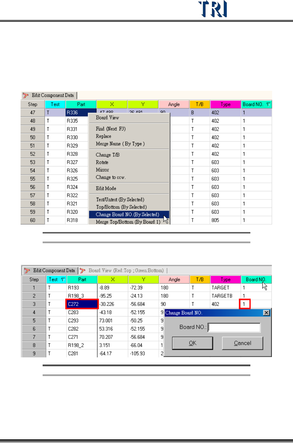
5.13 Change Board No. (Number)
Assign specific components to a specific board. Generally multi-board information is created
by the [Generate Multi-Board CAD Data] procedure, so that it is not necessary to change the
board number manually.
Figure 237: Select Change Board Number Command
Input the board number for the component that will be changed.
Figure 238: Change Board No. Dialog
Test Research Inc.
146 TR7500 Series User Guide –Software v.2.9.0
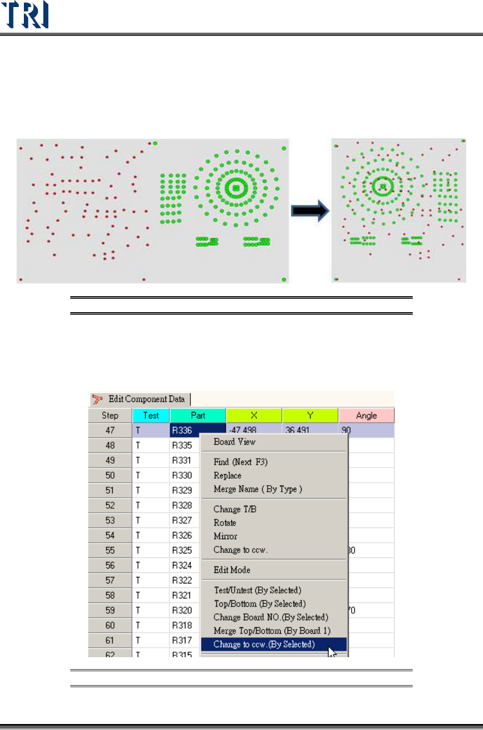
5.14 Merge Top/Bottom (By Board 1)
This function allows user to merge the spread CAD file into a regular [Top/Bottom] layout.
The user must first sort all data into a single board using the [T/B] function. Refer to the
following figure. The system will automatically mirror the bottom componenst behind the top
ones as red dots after [Merge Top/Bottom(By Board 1)] is selected.
Figure 239: Merge Top/Bottom Process
5.15 Change to CCW (By Selected)
Selecting this function will reverse from clockwise to counter-clockwise the angle of
components. The result will be a reduction in each selected component’s degrees.
Figure 240: Select Change to Counterclockwise