TR7500_Series_Software_v29_En - 第171页
Test Research Inc. TR7500 Series User Guide – Software v.2.9.0 149 Figure 245 : Delete Compon ent Dialog If there are several co mponents selected, the system w ill show the confirmed dialog. Figure 246 : Confirm Delete …
Test Research Inc.
148 TR7500 Series User Guide –Software v.2.9.0
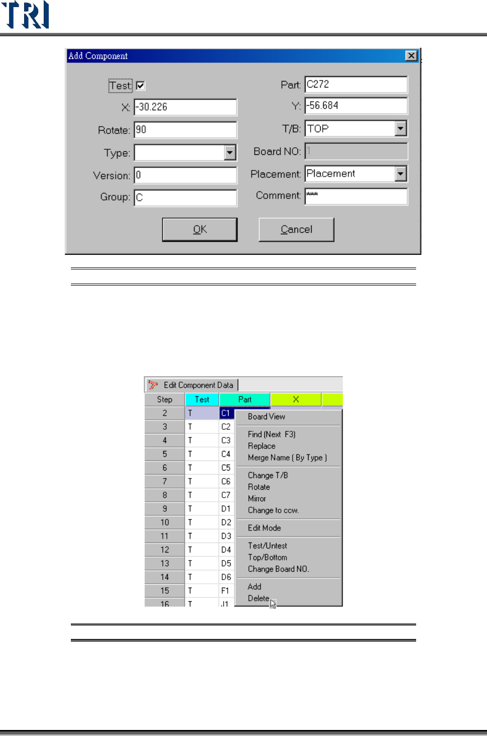
Figure 243: Add Component Dialog
5.17 Delete
Delete the component from the AOI component list table.
Figure 244: Select Delete Command
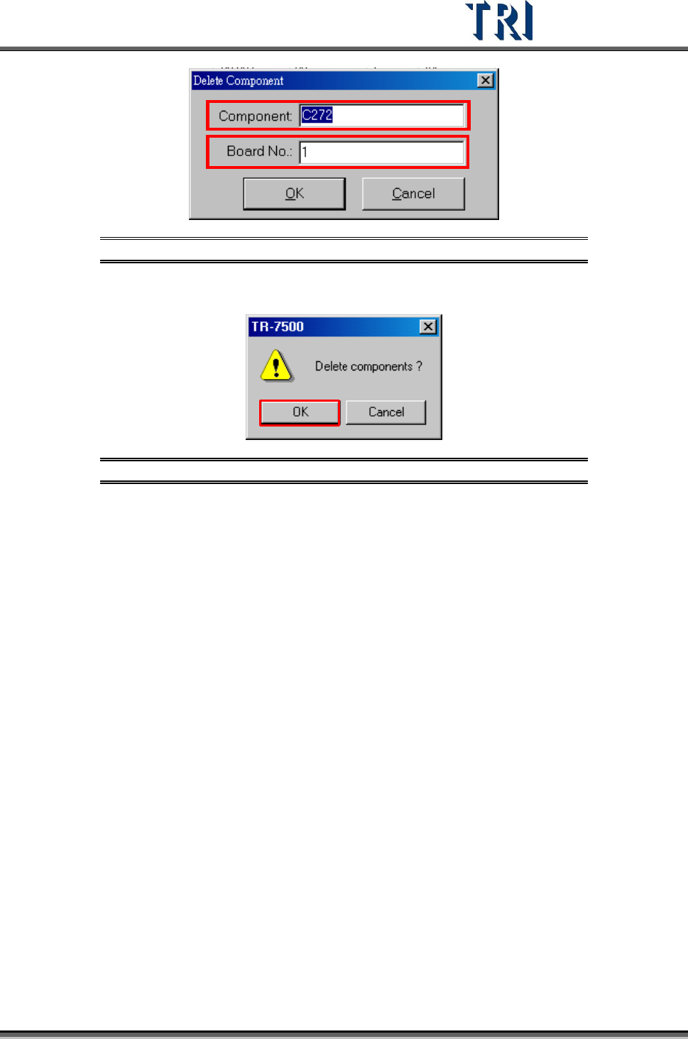
For a single component input the component name and board number that will be deleted.
Test Research Inc.
TR7500 Series User Guide –Software v.2.9.0 149
Figure 245: Delete Component Dialog
If there are several components selected, the system will show the confirmed dialog.
Figure 246: Confirm Delete Components Window
Test Research Inc.
150 TR7500 Series User Guide –Software v.2.9.0
6 G
ENERATE
M
ULTI
-B
OARD
CAD
D
ATA
6.1 Set
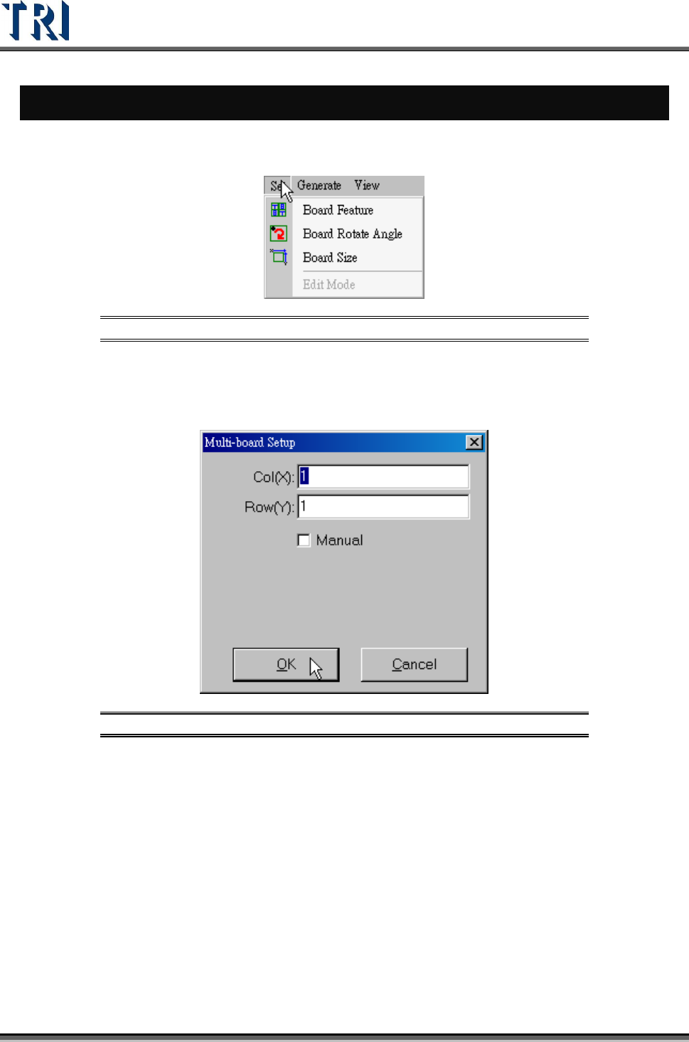
Figure 247: Set Command
6.1.1 Board Feature
Set the number of Columns and Rows here.
Figure 248: Multi-Board Setup Dialog
6.1.2 Board Rotate Angle
Calculate the board rotate angle again here.
6.1.3 Board Size
Set the board size again.
6.1.4 Edit Mode
After user modifies the multi-board layout, he has to select [Edit Mode] first. It only can be
changed under regular board and under an existing project.