TR7500_Series_Software_v29_En - 第227页
Test Research Inc. TR7500 Series User Guide – Software v.2.9.0 205 8.7.2 Algorithm D ialog: Procedure for Setti ng Logic Step1. Sel ect the inspection box es f or setting logic . (Press [Ctrl] on the keyboard and clic k …
Test Research Inc.
204 TR7500 Series User Guide –Software v.2.9.0
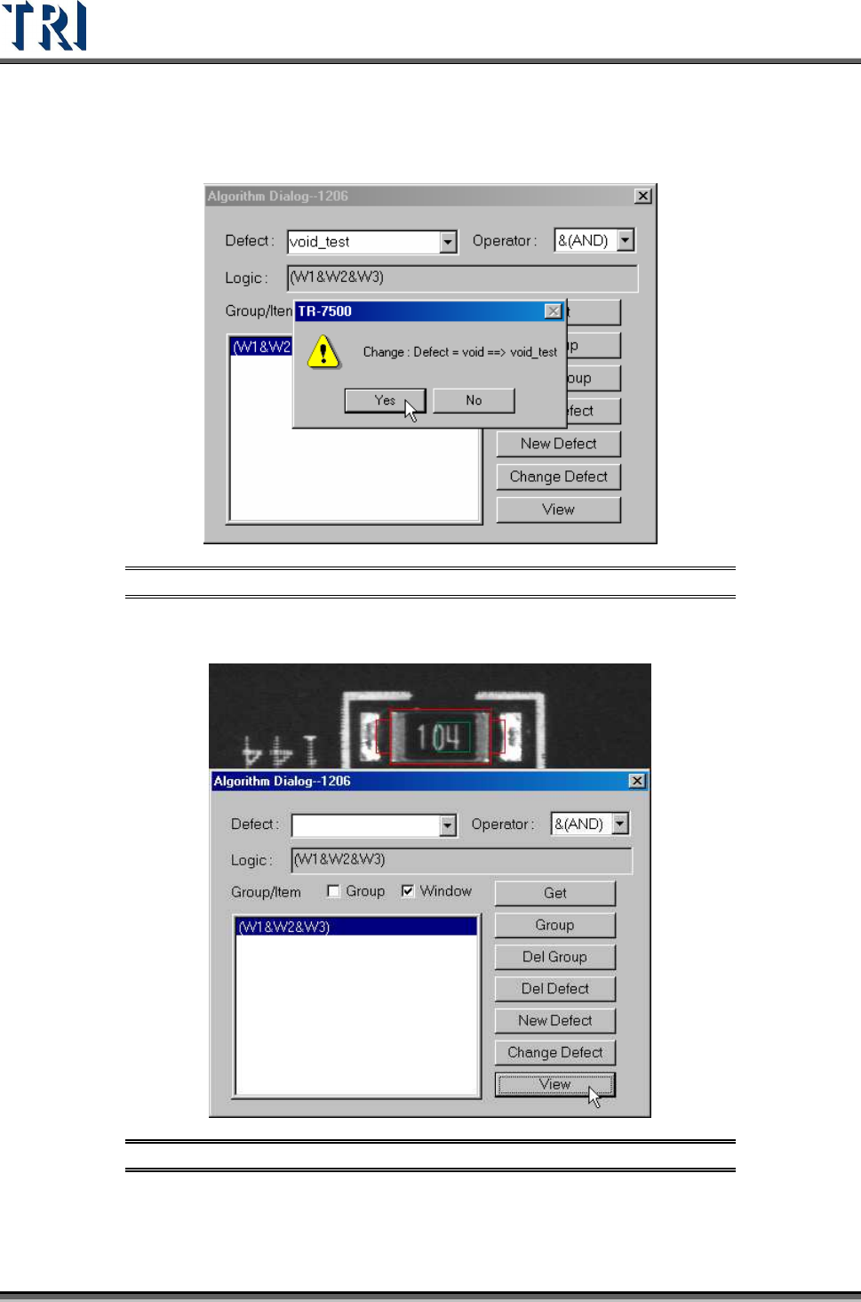
[Change Defect] – Changes the defect formula name.
Figure 344: Confirm [Change Defect]
[View] – Displays the inspection box for the defect formula.
Figure 345: View Inspection Box
Test Research Inc.
TR7500 Series User Guide –Software v.2.9.0 205
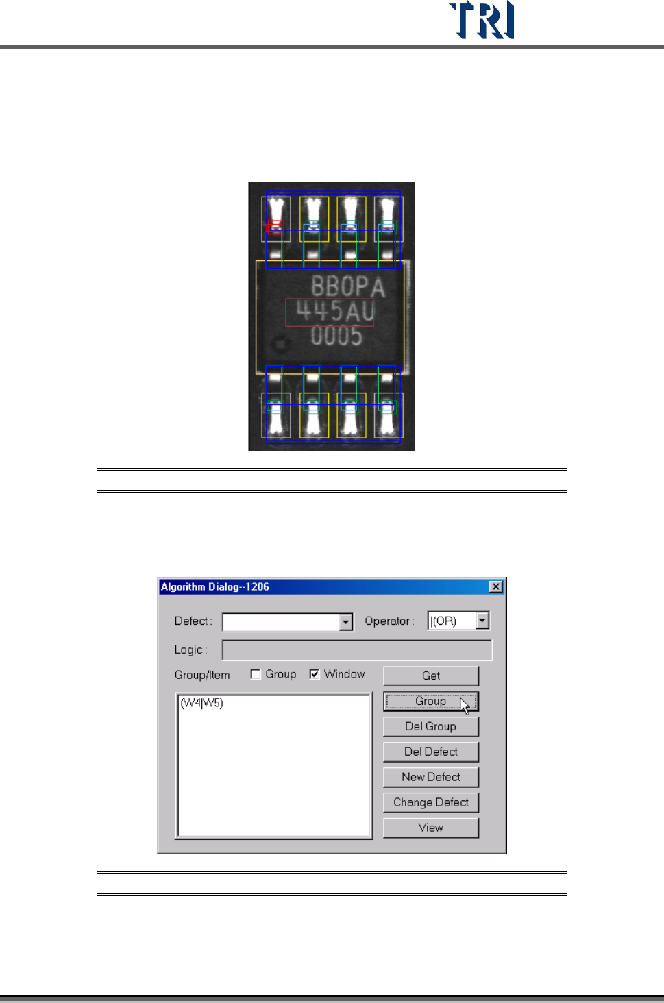
8.7.2 Algorithm Dialog: Procedure for Setting Logic
Step1. Select the inspection boxes for setting logic. (Press [Ctrl] on the
keyboard and click on the boxes to select them.)
Figure 346: Select Inspection Boxes
Step2. After selecting an [Operator], check the [Window] box and press [Group].
The inspection boxes will be composed by the specified [Operator] and
be listed in the window below.
Figure 347: Click on [Group] to Display Inspection Boxes
Step3. Double click on the formula that is listed in the window and the formula
will be copied to [Logic] field.
Test Research Inc.
206 TR7500 Series User Guide –Software v.2.9.0
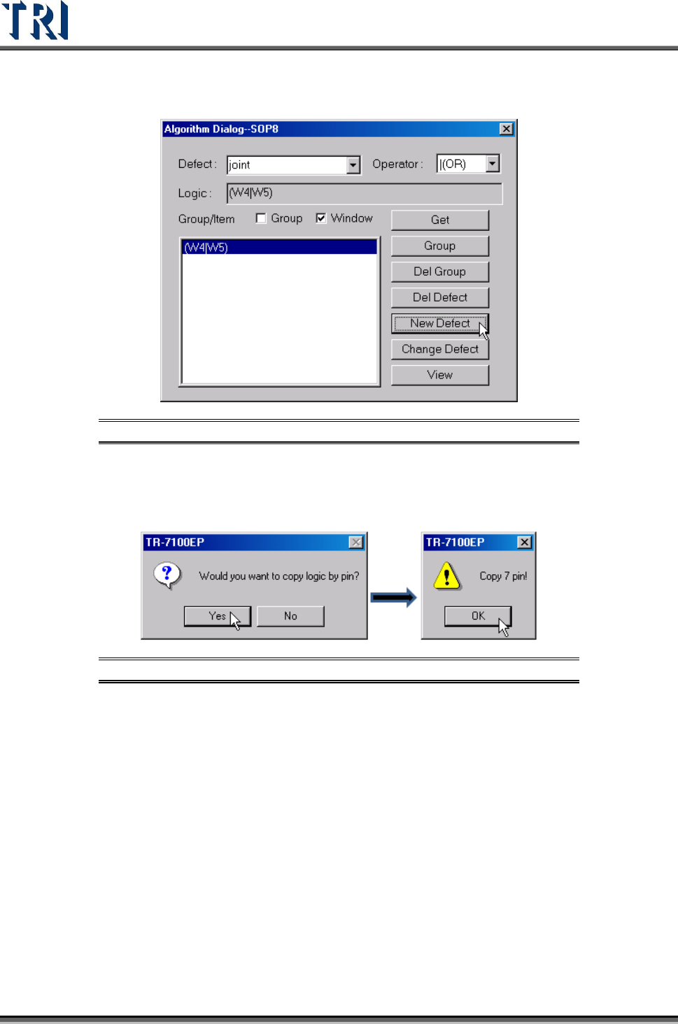
Step4. Give the new logic setting a name, and input it in [Defect] field. Then
press [New Defect] to create the new logic.
Figure 348: Add Name to [Defect] Field, Click on [New Defect]
Step5. When the logic contains an inspection box that belongs to an IC lead, the
system will ask if you want to copy the same logic to the other leads.
Select Yes or No according to the situation.
Figure 349: Copy IC Pin Logic