TR7500_Series_Software_v29_En - 第229页
Test Research Inc. TR7500 Series User Guide – Software v.2.9.0 207 8.7.3 Property Set the properties o f the inspection box . Figure 350 : Set Inspection Box Properties D ialog [(pin-1 ) ] – Display s the serial number…
Test Research Inc.
206 TR7500 Series User Guide –Software v.2.9.0
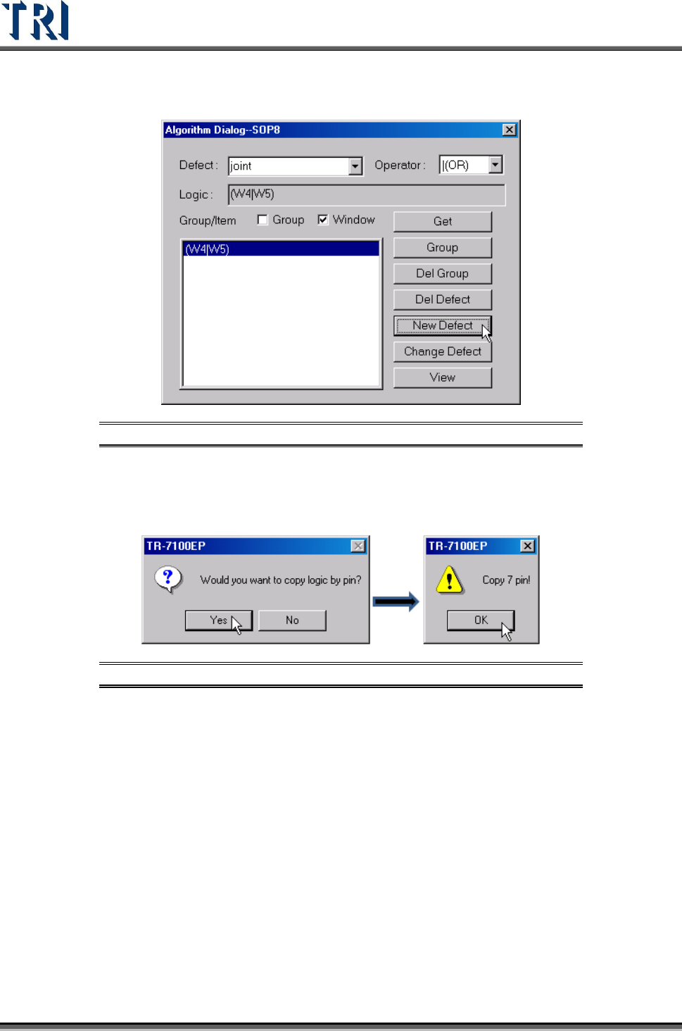
Step4. Give the new logic setting a name, and input it in [Defect] field. Then
press [New Defect] to create the new logic.
Figure 348: Add Name to [Defect] Field, Click on [New Defect]
Step5. When the logic contains an inspection box that belongs to an IC lead, the
system will ask if you want to copy the same logic to the other leads.
Select Yes or No according to the situation.
Figure 349: Copy IC Pin Logic
Test Research Inc.
TR7500 Series User Guide –Software v.2.9.0 207
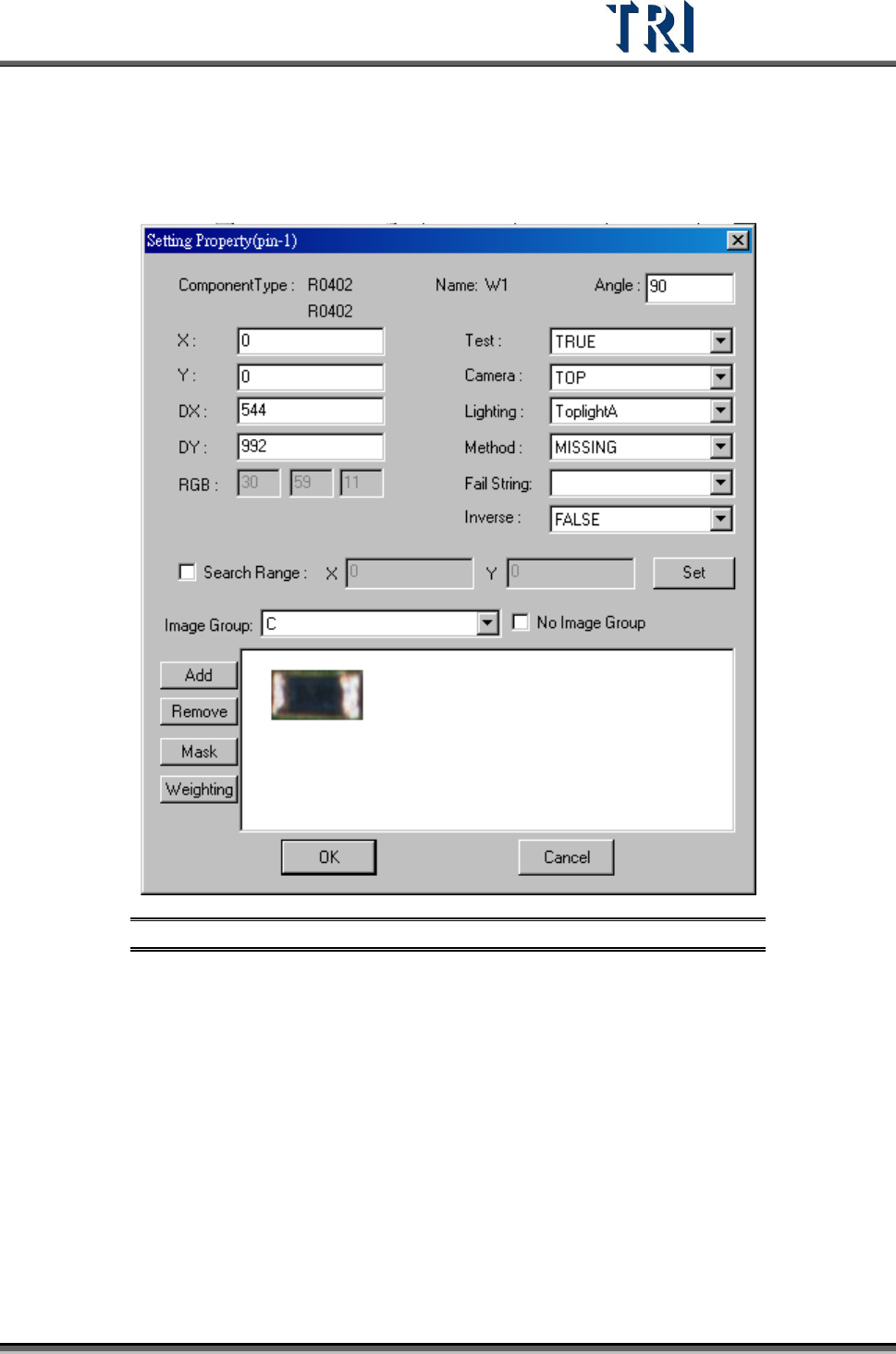
8.7.3 Property
Set the properties of the inspection box.
Figure 350: Set Inspection Box Properties Dialog
[(pin-1)] – Displays the serial number of the IC pin that the selected inspection
box inspects. When showing (pin-1), it means that the selected box doesn’t
inspect any IC pin.
[Component Type] – Displays the component type
[Name] – Displays the inspection box name
[Angle] – Displays the rotation angle of the component.
[X] – Component on the X coordinate position.
[Y] – Component on the Y coordinate position.
[DX] – The component X coordinate on the center.
[DY] –The component Y coordinate on the center.
[Test] – Select TRUE to enable inspection, FALSE to disable inspection.
Test Research Inc.
208 TR7500 Series User Guide –Software v.2.9.0
[Camera] – Select Top or Angle Camera view.
[Lighting] – Select Light type.
[Method] – Select the inspection windows for property change.
[Fail String] – Users can separate the same method into different fail strings
under [Library]. Each [Void] under the same component may have different [Fail
String] and will be labeled and sent to [Repair Station] as the changed one. Also,
changing the variables under the same algorithm will not affect the different [Fail
String]. The [Fail String] will remain default if the user decides not to change it.
[Inverse] – Turn on [Inverse] by selecting [True]. This will invert all the inspection
results. The inspection result of [Pass] will become to [Fail], and [Fail] to [Pass]
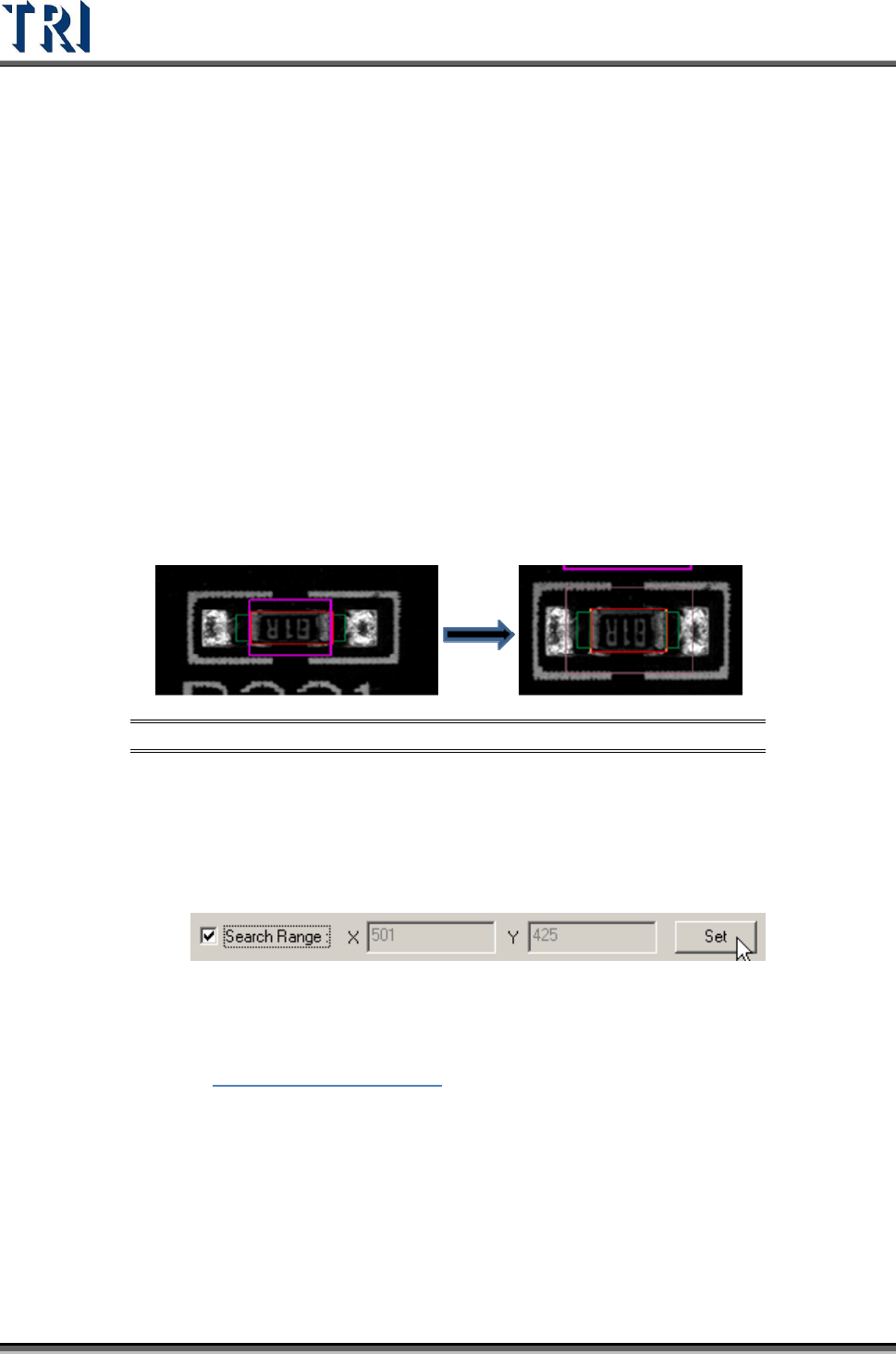
[Search Range] – Select this item to set the search range for [Missing] or [Lead]
box manually. After it is set, the latter X and Y fields display the range (unit: um).
The X and Y fields are just for review and cannot be filled. If the range is not set,
the X and Y field display “0” and the system sets the range automatically.
Step1. Open [Property] dialog and check [Search Range]. A thick line and purple
frame appear on the painted area.
Figure 351: Select & Display [Search Range]
Step2. Click on the box to set and then adjust the purple frame to suit the search
range. The search range cannot be smaller than the inspection box.
Step3. Press [Set] then the setting is finished. The X and Y field display the length
and width of the search range.
Step4. The search range is displayed by a thin line and purple frame.
[Image Group] – When the components have the same type but are in different
groups, the image must be set for different groups. See more about groups in
Chapter
5 Edit Component Data
[No Image Group] – After choosing this, users may select [Group] which
contains only those without image taken. For example, if there are two groups of
C and R under Type 0402, and C already has an image taken, but R does not.
The user may only see R under [Group] if the [No Image Group] is selected.
[ADD] – Add image to component image library from missing or lead inspection
windows.
[Remove] – Remove the select image to component image library.