TR7500_Series_Software_v29_En - 第23页
Test Research Inc. TR7500 Series User Guide – Software v.2.9.0 1 1 I NTRODUCT ION Test Research Inc.’s ( TRI) TR7500 serie s of high-speed, Au tomated Optical Inspec t ion test systems currently includes the TR7500, T R7…

Test Research Inc.
xviii TR7500 Series User Guide –Software v.2.9.0
Figure 467: Default Mask Zone ..........................................................................................276
Figure 468: Mask Dark Zone ..............................................................................................277
Figure 469: Mask Bright Zone ............................................................................................277
Figure 470: ROI Parameters Dialog....................................................................................277
Figure 471: Switch FOV Panel ...........................................................................................279
Figure 472: Merge Library Dialog .......................................................................................280
Figure 473: Histogram Curve..............................................................................................281
Figure 474: Change FOV Lighting ......................................................................................282
Figure 475: Save Lighting Name Options ...........................................................................283
Figure 476: Load a Saved Image .......................................................................................285
Figure 477: Save a New Image from Image Area...............................................................286
Figure 478: Auto-Search & Change Type...........................................................................287
Figure 479: Information Bar...............................................................................................289
Figure 480: Examples of Weighting: Mono (left) & RGB .....................................................289
Figure 481: Image Diagram Functions................................................................................290
Figure 482: Panel Defect Map ............................................................................................291
Figure 483: Test Results Dialog .........................................................................................292
Figure 484: PPY Defect Statistics.......................................................................................293
Figure 485: FPY Defect Statistics.......................................................................................293
Figure 486: Example: Defect Tree......................................................................................294
Figure 487: Results Screen with Yield & Fail Statistics Hidden...........................................294
Figure 488: Use HCI to Set Conveyor Width ......................................................................295
Figure 489: Confirm Save Conveyor Width.........................................................................296
Figure 490: Confirm Auto-Set Conveyor Width...................................................................296
Figure 491: Push Reset on HCI to Start X-Y Table.............................................................297
Figure 492: Click on Open File Icon, Select Project to Open ..............................................298
Figure 493: Click Inspect Button.........................................................................................298
Figure 494: Press TEST Button..........................................................................................298
Figure 495: Select Fiducial Mark Alignment........................................................................299
Figure 496: Select Fiducial Mark Setting ............................................................................299
Figure 497: Connect TR7500 with Offline Editor PC...........................................................302
Figure 498: Offline Station Dialog.......................................................................................303
Figure 499: Lighting Compensation Parameters.................................................................305
Figure 500: Camera Alignment Dialog................................................................................306
Figure 501: Confirm Save Gray Card Position....................................................................307
Figure 502: Confirm Perform Lighting Compensation 1 ......................................................307
Figure 503: Confirm Perform Lighting Compensation 2 ......................................................307
Figure 504: Confirm Perform Lighting Compensation 3 ......................................................308

Test Research Inc.
TR7500 Series User Guide –Software v.2.9.0 1
1 I
NTRODUCTION
Test Research Inc.’s (TRI) TR7500 series of high-speed, Automated Optical Inspection test
systems currently includes the TR7500, TR7500E, TR7500L, and TR7501. Desktop models
include the TR7500DT and TR7500DTL. They incorporate TRI’s Read-on-the-Fly™ scanning
for vibration-free imaging of Printed Circuit Boards and Assemblies (PCBs/PCBAs) . For
details of each model, please reference the relevant specification.
For purposes of convenience, this guide will use “TR7500” to refer to all models. This User
Guide—Software provides information on TR7500’s Software Features. Features which are
only for the non-DT models are specified as “TR7500 Series only”.
Test Research Inc.
2 TR7500 Series User Guide –Software v.2.9.0
2 AOI
S
TANDARD
P
ROJECT
C
REATION
The Automatic Test Program Generator (ATPG) is a powerful tool incorporated into the
TR7500 system. This chapter explains how ATPG works.
2.1 Project Creation & Start with ATPG
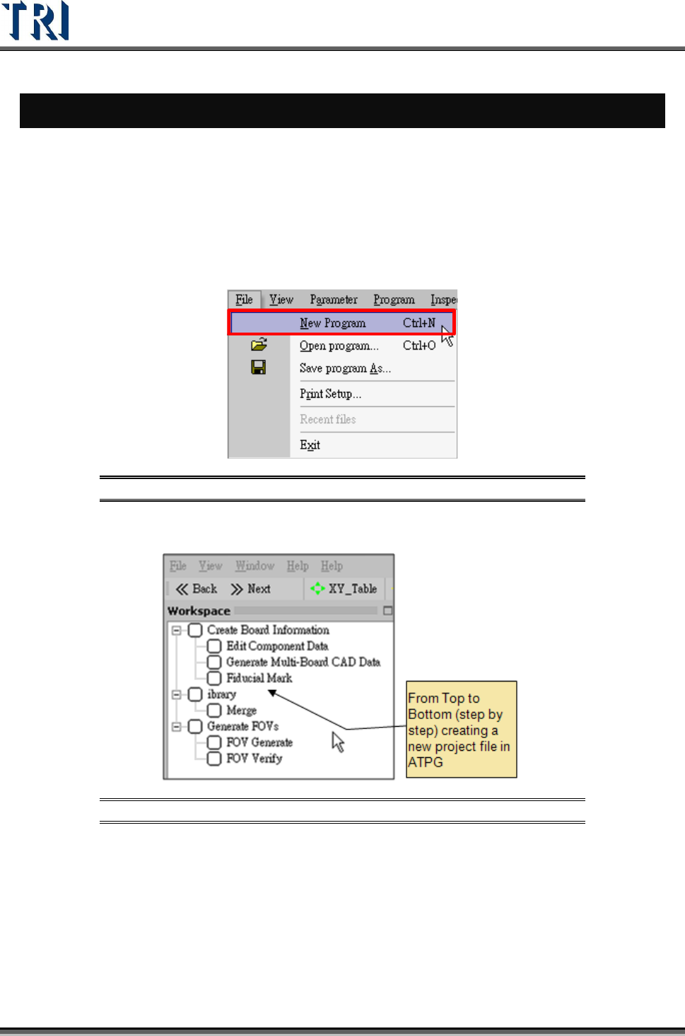
1. Double click on the shortcut of TR7500 main program.
2. Create a new project file.
Figure 1: Creating a New TR7500 Program File
3. ATPG steps appear.
Figure 2: List of ATPG Steps
4. Confirm loading CAD file dialog window.