TR7500_Series_Software_v29_En - 第238页
Test Research Inc. 216 TR7500 Series User Guid e –Softwa re v.2.9.0 8.8.7 Angle Display the angle of the current componen t . Change the value to see the rotation of inspection boxes, bu t the real angle ca n’t be change…
Test Research Inc.
TR7500 Series User Guide –Software v.2.9.0 215
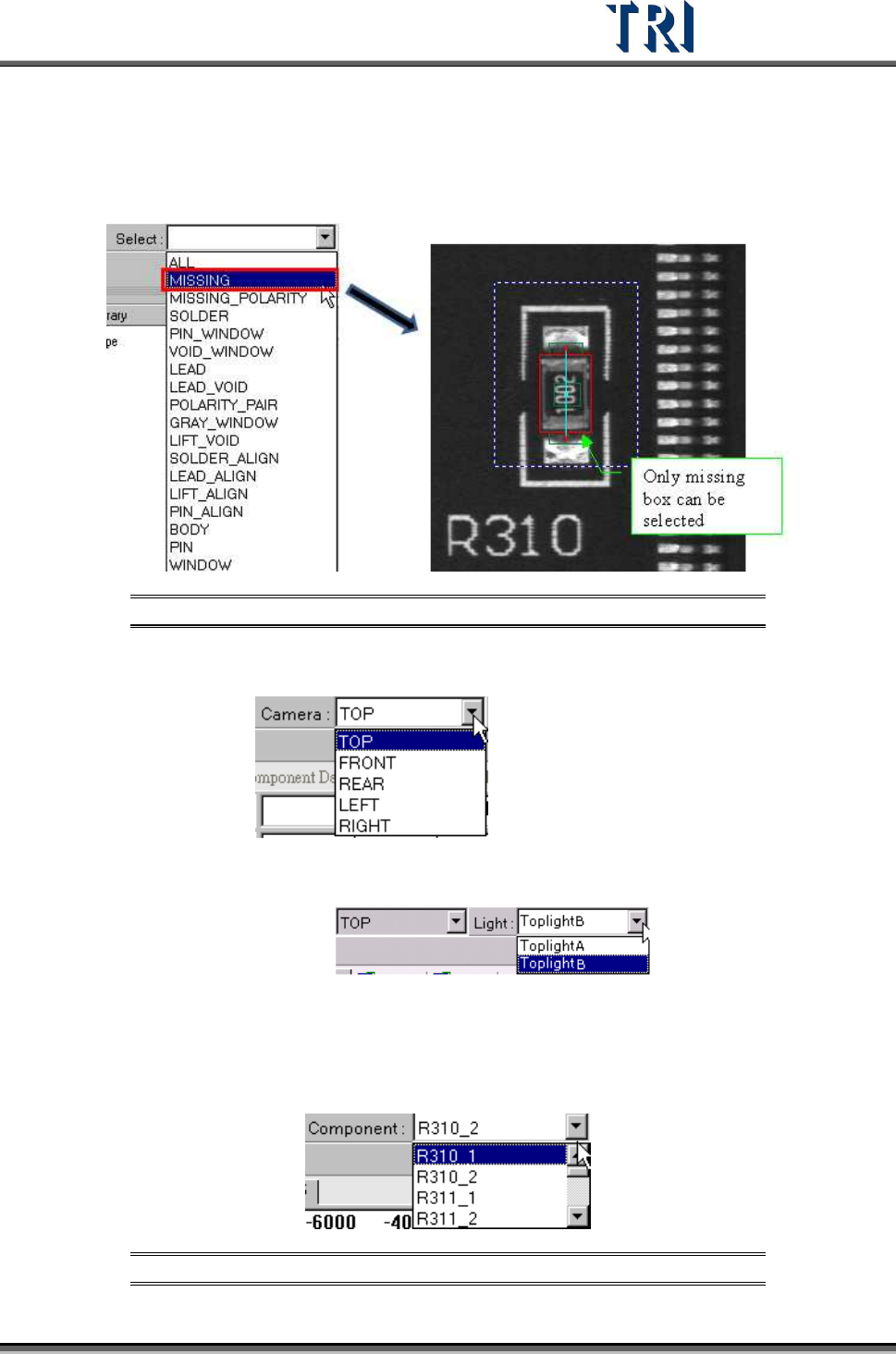
8.8.3 Select
Choose a specific kind of window to be selected.
Figure 362: Select Window Type
8.8.4 Camera
Select camera to display
8.8.5 Light
Choose a specific light to display:
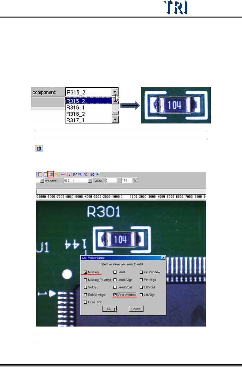
8.8.6 Component
Select any component in this type according to CAD file. The camera will move to grab the
image of a specific component.
Figure 363: Select Component Type
Test Research Inc.
216 TR7500 Series User Guide –Software v.2.9.0
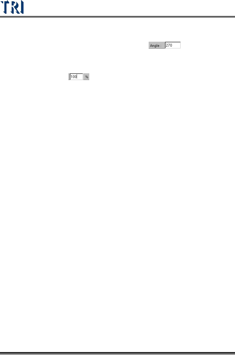
8.8.7 Angle
Display the angle of the current component. Change the value to see the rotation of
inspection boxes, but the real angle can’t be changed here:
8.8.8 % (Percent)
Change the value to reduce or enlarge the size of all boxes. When the library is saved, the
current size will be saved:
Test Research Inc.
TR7500 Series User Guide –Software v.2.9.0 217
8.9 Example: Edit Component Library
8.9.1 Example 1 – Chip
(1) Choose a component that is not shifted or skewed and has a clear, clean shape.
(2) Then resize the [Body] window to match the component area.
Figure 364: Choose a Component, Resize Body Window
(3) Press [Add all] to add [Missing] and [Void] windows. The system will create one
[Missing] window on the [Body] window and two [Void] windows, one on each of the two
short sides of the [Missing] window.
Figure 365: Add Missing & Void Windows