TR7500_Series_Software_v29_En - 第243页
Test Research Inc. TR7500 Series User Guide – Software v.2.9.0 221 (3) Select the first pin and p ress [Mirror Copy] by Y di r ection to copy the pin t o the last lead area. Or click on [Add Pin] to add one pin again, th…
Test Research Inc.
220 TR7500 Series User Guide –Software v.2.9.0
8.9.2 Example 2 - IC
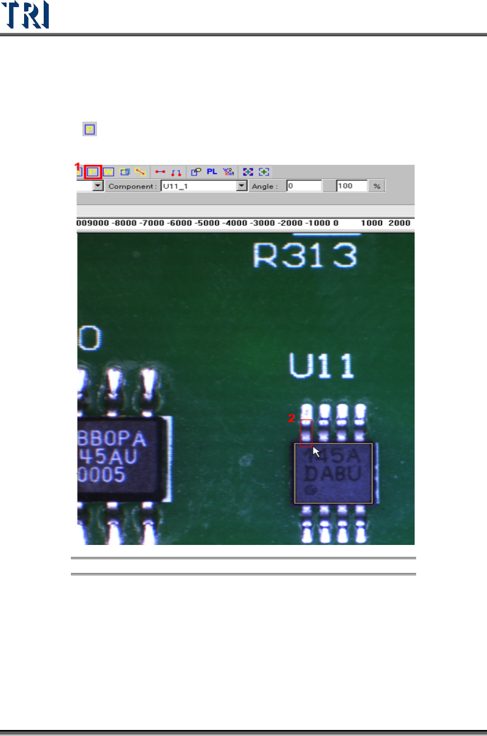
(1) Choose a component that is not shifted or skewed and has a clean, clear shape. Then
resize the body window to match the component area.
(2) Click on
[Add Pin] to add one pin then move and resize the pin to match the first
lead area.
Figure 370: Add & Resize Pin
Test Research Inc.
TR7500 Series User Guide –Software v.2.9.0 221
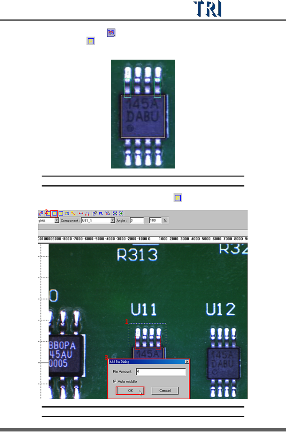
(3) Select the first pin and press [Mirror Copy] by Y direction to copy the pin to the last
lead area. Or click on
[Add Pin] to add one pin again, then move and resize the box
to match the last lead area.
Figure 371: Use [Mirror Copy] to Set Pins in First & Last Lead Area
(4) Choose the two pins at end of the side then click on [Add Pin] to add more pins.
Figure 372: Choose First & Last Pins, Add Pins
Test Research Inc.
222 TR7500 Series User Guide –Software v.2.9.0
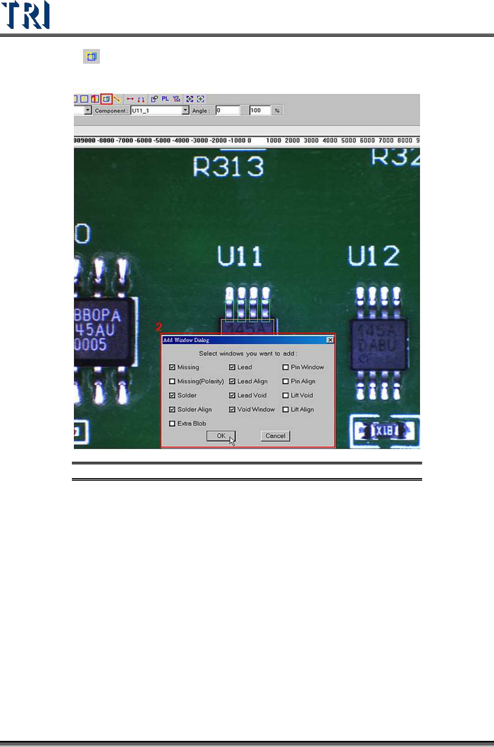
(5) Click on [Add all] to add inspection windows, including [Missing (Polarity)], [Solder],
[Solder Align], [Lead], [Lead Align], and [Lead Void].
Figure 373: Add Inspection Windows
(6) Resize and set parameters for every kind of inspection window.
[Lead]
Select lead and top camera then drag mouse to highlight the lead box.
Set parameters in the [Property] dialog.
[Lead Void]
Select lead void then drag mouse to highlight the lead void box.
Resize the lead void box.
Set parameters in the [Property] dialog.
[Solder]
Select solder and rear camera then drag mouse to highlight the solder box.
Resize the solder box.
Set parameters such as test and lighting in the [Property] dialog.