TR7500_Series_Software_v29_En - 第249页
Test Research Inc. TR7500 Series User Guide – Software v.2.9.0 227 Figure 378 : Model Image P ass Level Set tings [Si m ilarity] – The simila rity betw een standard image and inspec ted ima g e. [Shi f t X] – The tol…
Test Research Inc.
226 TR7500 Series User Guide –Software v.2.9.0
9 I
MAGE
M
ATCHING
P
RINCIPLES AND
P
ASS
L
EVEL
S
ETTINGS
9.1 Methods of Image Matching
9.1.1 Method 1–Geometric Feature Matching
The system saves the pattern and features of the image and inspects the image according to
the features. [Missing] is inspected using this algorithm. Also, this algorithm can be selected
to do image matching for [Warp].
9.1.2 Method 2–Normalize Correlation Matching
System learns the gray level(s) and feature(s) of the image, then finds the best matching
object in the search range when inspecting. [Lead] is inspected with this algorithm and this
algorithm can be selected to do image matching for [Warp].
9.1.3 Method 3–Projection Profile Matching
After projecting the gray level to the X and Y axis, the system takes the projections as the
features to inspect. [Align] is inspected with this algorithm.
9.2 Principles and Settings
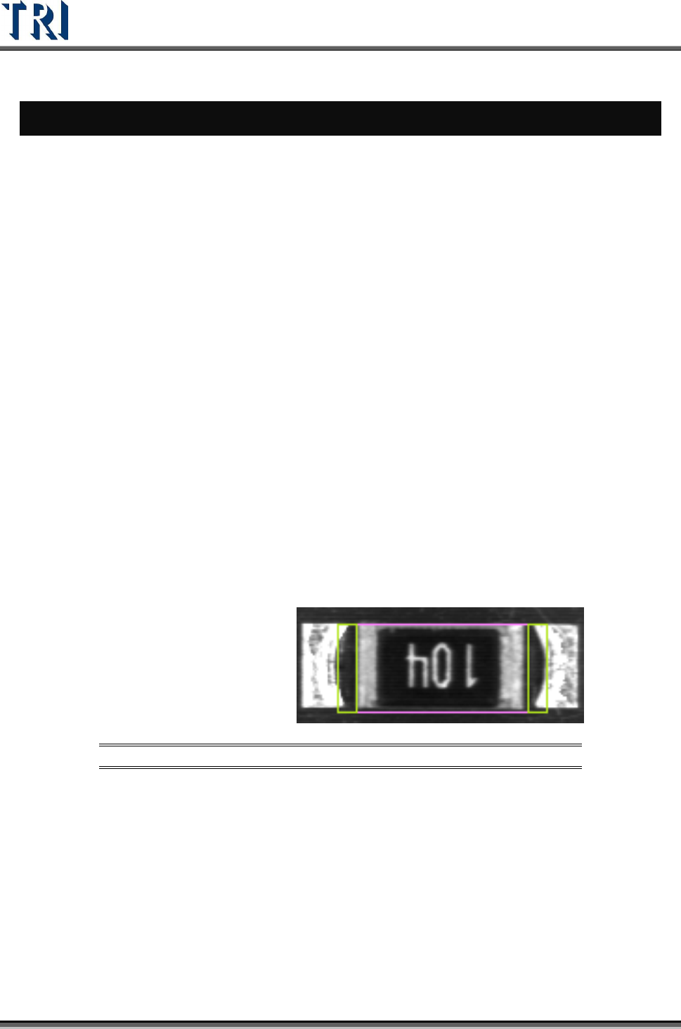
9.2.1 Model Image (Missing/Missing Polarity)
To check the missing, shift, tombstone and polarity of components. Use the Geometric
Feature Method (Method 1). Grab a good image model for sample. Compare with test
component to find the defect.
Figure 377: Model Image (Missing) Window
The [Pass Level Settings] are shown in the following figure.
Test Research Inc.
TR7500 Series User Guide –Software v.2.9.0 227
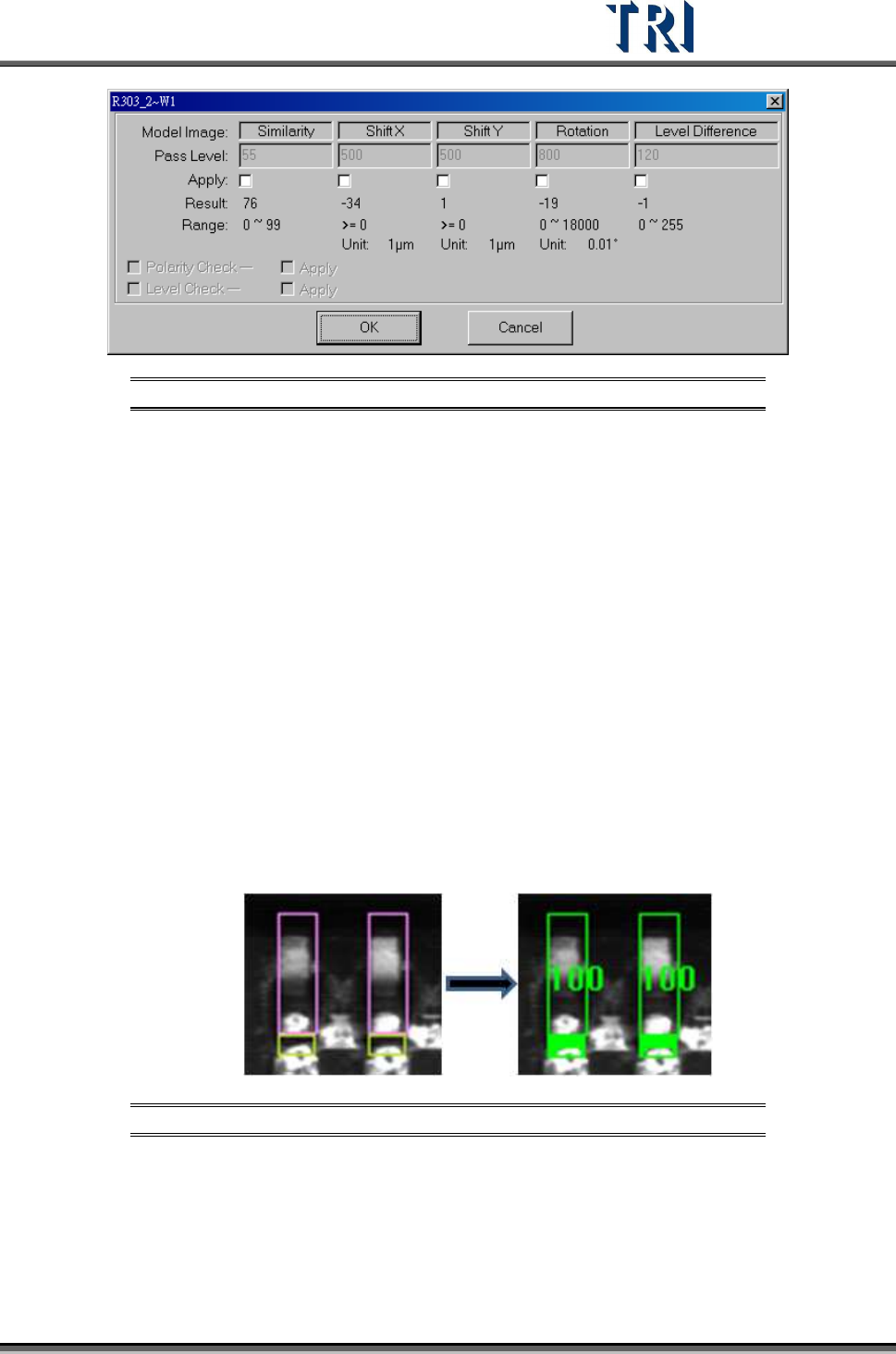
Figure 378: Model Image Pass Level Settings
[Similarity] – The similarity between standard image and inspected image.
[Shift X] – The tolerance of shift on x direction.
[Shift Y] – The tolerance of shift on y direction.
[Rotation] – The tolerance of rotate angle
[Level Difference] – System will save the gray level average of a 10x10 pixel
area at the center of the box for inspecting. For example, if the trained value is
100 and the level difference tolerance is 35. It means the system will show fail
when the result is over 135 or less than 65.
[Polarity Check] – If the component is rotated 180 degrees it will be judged as a
defect.
[Level Check] – Select to open the [Level Difference] function.
9.2.2 Lead
Checks missing, shift and bending of IC leads. Use image correlation method (Method2).
grab a good image model for sample. Compare with test lead to find the
defect.
Figure 379: Compare Lead Images
The [Pass Level Settings] are shown in the following figure.
Test Research Inc.
228 TR7500 Series User Guide –Software v.2.9.0
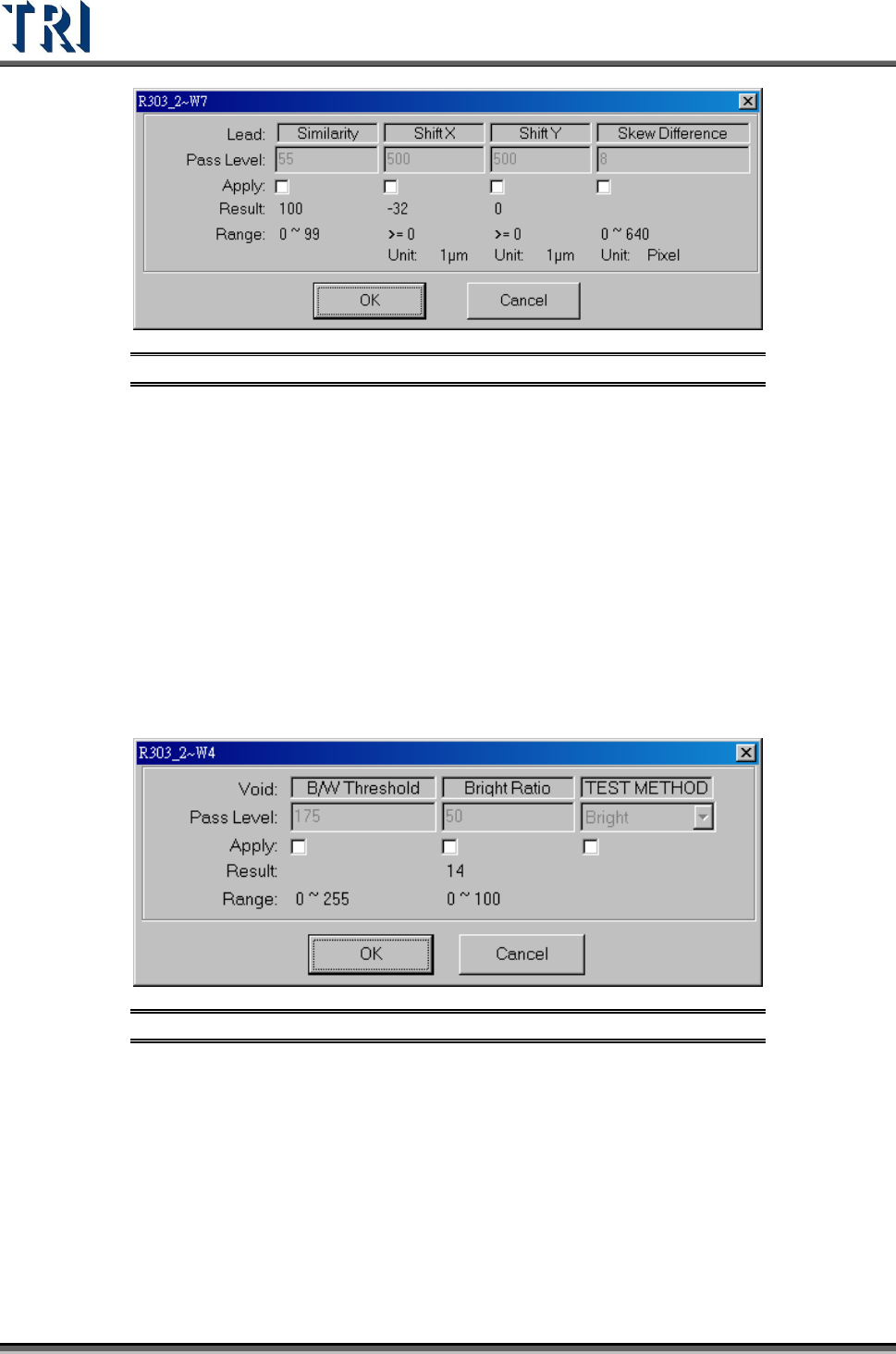
Figure 380: Lead Pass Level Settings
[Similarity] – The similarity between the standard image and the inspected image.
[Shift X] – The tolerance of shift on X direction.
[Shift Y] – The tolerance of shift on Y direction.
[Skew Difference] – The tolerance of position difference between adjacent boxes.
9.2.3 Void
Checks for no solder, open, and/or polarity of components. Uses the levels set in [B/W
Threshold] and [Bright Ratio] to find the defect. Bright/Dark is a method to find the
darkness/brightness.
The [Pass Level Settings] are shown in the following figure.
Figure 381: Void Pass Level Settings
[B/W Threshold] – Set the threshold to judge the black and white.
[Bright Ratio] – Set the tolerance of white ratio.
[TEST Method]
[Bright] – If the white ratio is over the tolerance, the inspection box will be
regarded as failed.
[Dark] –If the white ratio is lower than the tolerance, the inspection box will be
regarded as failed.