TR7500_Series_Software_v29_En - 第255页
Test Research Inc. TR7500 Series User Guide – Software v.2.9.0 233 Figure 390 : ROI Parameter Dialog [ T rain] –Set the para meter for training [Sensitivity ] – Using 70 as an example. If the difference of g ray level …
Test Research Inc.
232 TR7500 Series User Guide –Software v.2.9.0
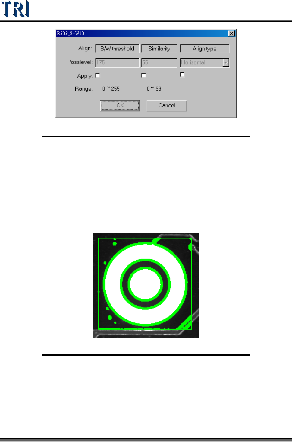
Figure 388: Align Pass Level Settings
9.2.9 Warp
The assumption is that the warp in one FOV is the same. Each component has a relationship
with the warp model. During inspection, [Warp] will calculate the shift distance in the X-Y
direction. Each component will have the shift added, then start to test for pass/fail.Select
Method 1 or Method 2 to do pattern matching. AN FOV to be inspected with an angle camera
must use [Warp]. [Warp] can only be added in [Train] dialog.
9.2.10 ROI
[ROI] is an inspection box to inspect the scrape of surface.
Figure 389: ROI Inspection Box
The [ROI Parameters] are shown in the following figure.
Test Research Inc.
TR7500 Series User Guide –Software v.2.9.0 233
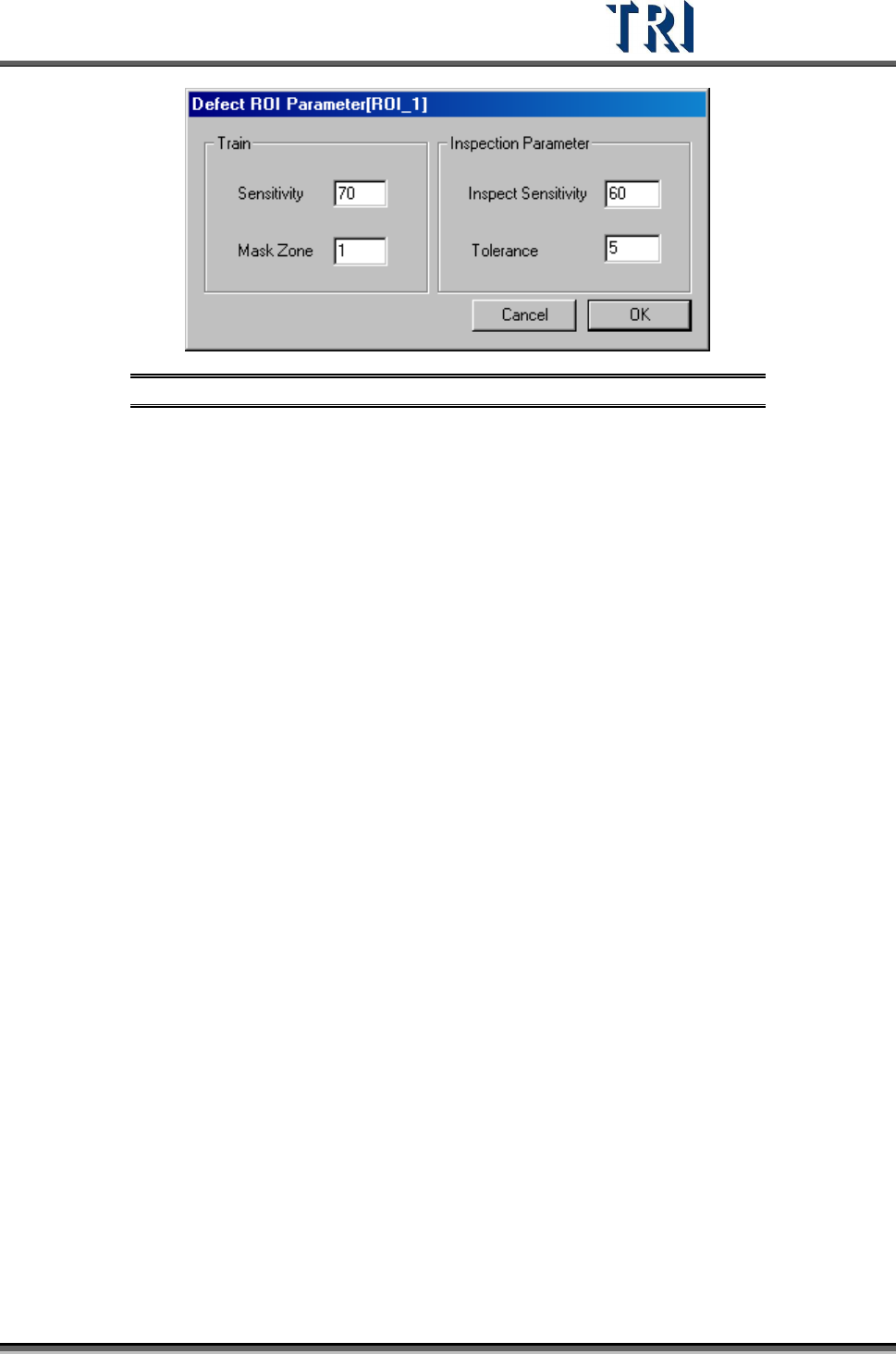
Figure 390: ROI Parameter Dialog
[Train] –Set the parameter for training
[Sensitivity] – Using 70 as an example. If the difference of gray level between
neighboring pixels is larger than 30 (100-70) the two pixels will be
regarded as edges.
[Mask Zone] – Using 1 as an example. Next to the edge points, the adjacent 1
pixel is masked as Untest.
[Inspection Parameter] – Set the parameter for inspection. The system only
inspects the area that is in an ROI box and not masked.
[Inspect Sensitivity] – Using 60 as an example. If the difference of gray level
between adjacent pixels is larger than 40 (100-60) the two pixels will be
regarded as edges.
[Tolerance] – Using 5 as an example. If a group size of edges is more than 5
the inspection window will be regarded as failed.
The [Sensitivity] value must be bigger than [Inspect Sensitivity] or it will result in
more false calls.
Test Research Inc.
234 TR7500 Series User Guide –Software v.2.9.0
9.2.11 Extra Blob
[Extra Blob] is an inspection box to inspect lead open or the scratch of surface.
The [Pass Level Settings] are shown in the following figure.
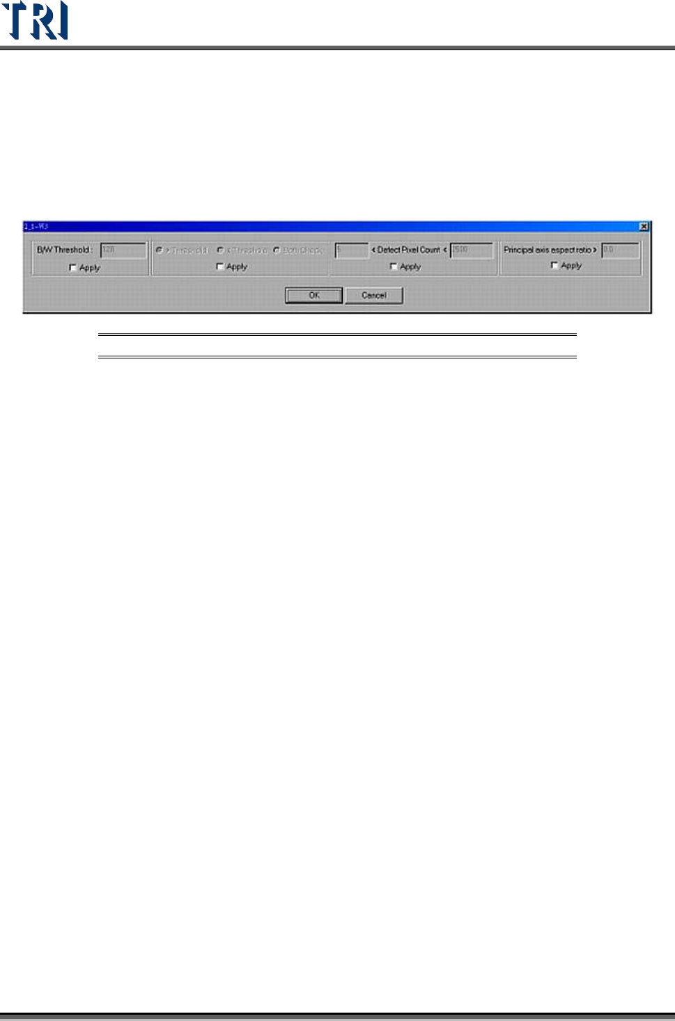
Figure 391: Extra Blob Window Settings
[B/W Threshold] – Input the bright and white threshold
[>Threshold] – Choose this to select the pixels which have a greater gray level
than threshold value.
[<Threshold] – Choose this to select the pixels which have a lower gray level
than the threshold value.
[Both] – Choosing this is to express that you care about the pixel which has
greater or smaller gray level than threshold value and conforms to the following
conditions.
[<Defect Pixel Count<] – The system marks the pixels that are not confirmed
with threshold and regards the adjacent marked pixels as a group. Input the
minimum and maximum. When the size of a group is located in the range, that
group is regarded as a fail. For example, set “50< Defect Pixel Count<500”. This
means that the marked group will be regarded as fail when the group size is
between 50 to 500 pixels.
[Principal axis aspect ratio>] –When the ratio of width to length of a defect group
is larger than the input value, the group will be regarded as a fail. This function
can catch the white line which appears when an IC pin lifts. Input 0 when you do
not want to use this function.
9.2.12 Edge Window
The [Edge Window] is used to check pixels on the edges of inspection windows. The
inspection box parameter setting is shown in the following figure.