TR7500_Series_Software_v29_En - 第257页
Test Research Inc. TR7500 Series User Guide – Software v.2.9.0 235 Figure 392 : Edge Window Dialog [Edge Threshold] – T he difference of ad jacent pixels [Edge Pixel Count Tolerance] – The sy stem will count all the …
Test Research Inc.
234 TR7500 Series User Guide –Software v.2.9.0
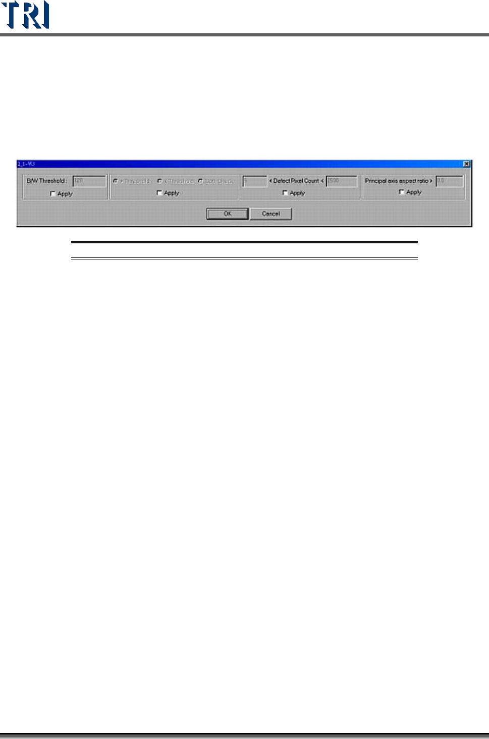
9.2.11 Extra Blob
[Extra Blob] is an inspection box to inspect lead open or the scratch of surface.
The [Pass Level Settings] are shown in the following figure.
Figure 391: Extra Blob Window Settings
[B/W Threshold] – Input the bright and white threshold
[>Threshold] – Choose this to select the pixels which have a greater gray level
than threshold value.
[<Threshold] – Choose this to select the pixels which have a lower gray level
than the threshold value.
[Both] – Choosing this is to express that you care about the pixel which has
greater or smaller gray level than threshold value and conforms to the following
conditions.
[<Defect Pixel Count<] – The system marks the pixels that are not confirmed
with threshold and regards the adjacent marked pixels as a group. Input the
minimum and maximum. When the size of a group is located in the range, that
group is regarded as a fail. For example, set “50< Defect Pixel Count<500”. This
means that the marked group will be regarded as fail when the group size is
between 50 to 500 pixels.
[Principal axis aspect ratio>] –When the ratio of width to length of a defect group
is larger than the input value, the group will be regarded as a fail. This function
can catch the white line which appears when an IC pin lifts. Input 0 when you do
not want to use this function.
9.2.12 Edge Window
The [Edge Window] is used to check pixels on the edges of inspection windows. The
inspection box parameter setting is shown in the following figure.
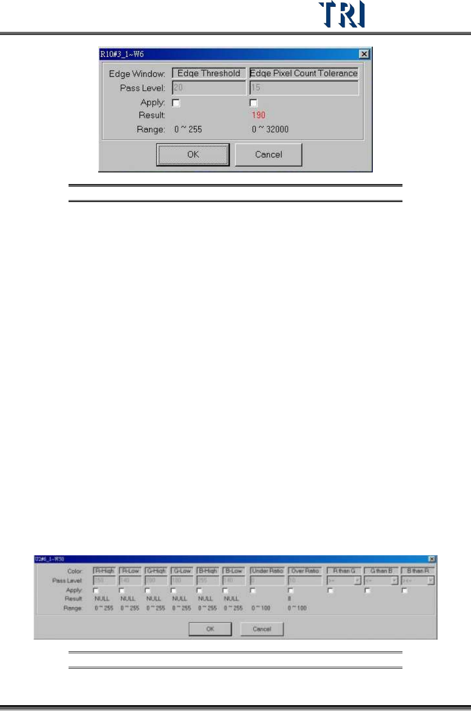
Test Research Inc.
TR7500 Series User Guide –Software v.2.9.0 235
Figure 392: Edge Window Dialog
[Edge Threshold] – The difference of adjacent pixels
[Edge Pixel Count Tolerance] – The system will count all the pixels included by the
[Edge Threshold], and show “Fail” if the count is over the [Edge Pixel Count Tolerance]
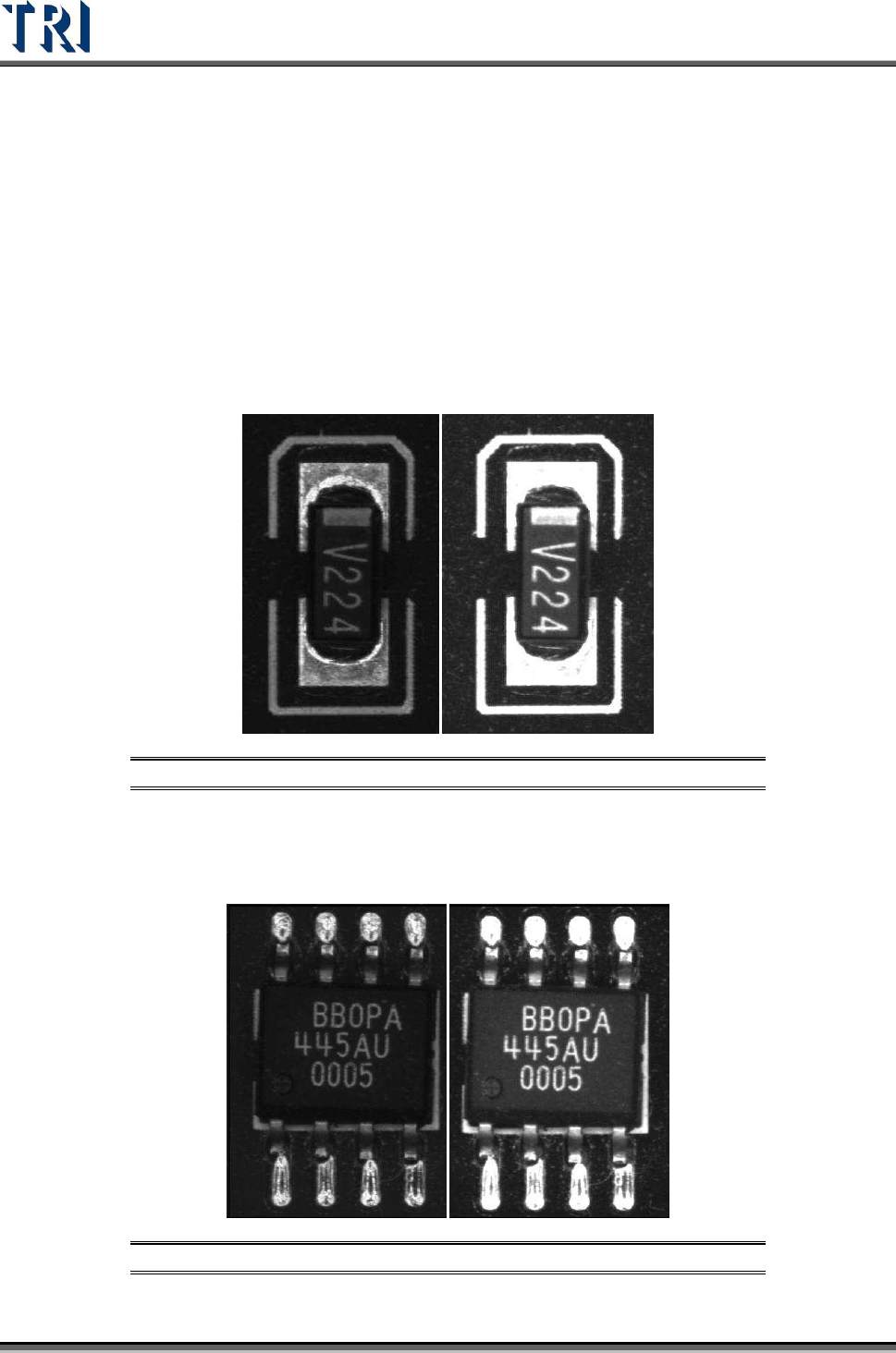
9.2.13 Color Window
This function calculates the ratio of different colors found in a specific color.
The condition of Pixels’ R, G and B Value within the inspection box
[R-High] >= [R value] > [R-Low]
[G-High] >=
[G value] > [G-Low]
[B-High] >=
[B value] > [B-Low]
To meet the R than G,G than B,B than R conditions
Conditions
If (R ><=G), then ignore R&G relation //default
If (R >=G), then
[R value] >= [G value] + ([R-Low]-[G-Low])
If (R <=G), then
[R value] <= [G value] + ([R-Low)-[G-Low))
If (G ><=B), then don’t care G&B relation //default
If (G>=B), then
[G value] >= [B value] + ([G-Low]-[B-Low])
If (G <=B), then
[G value] <= [B value] + ([G-Low)-[B-Low))
If (B ><=R), then don’t care B&R relation //default
If (B >=R), then
[B value] >= [R value] + ([B-Low]-[R-Low])
If (B <=R), then
[B value] <= [R value] + ([B-Low]-[R-Low))
Areas which are over the [Over Ratio] or under [Under Ratio] are “Fail”.
Figure 393: Color Window Pass Levels
Test Research Inc.
236 TR7500 Series User Guide –Software v.2.9.0
9.3 Color Check Method and RGB Weighting
9.3.1 Color Check Method
The Top-View camera consists of three CCD light-sensors. Unlike monochrome cameras,
they tend to have much better contrast in images by regulating the RGB Weighting.
Inspection boxes that are specially created using the top CCD camera will have better quality
sample images, and better to use for comparisons. Hence, the camera can easily detect
major contrasts on failing components. This is called CCM (Color Check Method).
Using a resistor chip as an example, the image to the left was captured by a monochrome
camera, and the image to the right was captured by a three color sensor CCD camera and
regulated by RGB Weighting.
Figure 394: Resistor: Monochrome Image (left) & 3-Color CCD Image
Using an SOP designator as an example, the image to the left was captured by a
monochrome camera, and the image to the right was captured by a three color sensor CCD
camera and regulated by RGB Weighting.
Figure 395: SOP Designator: Monochrome Image (left) & 3-Color CCD Image