TR7500_Series_Software_v29_En - 第261页
Test Research Inc. TR7500 Series User Guide – Software v.2.9.0 239 In general, the RGB W eighting function may reinforce the result of the colo r reflection of components, makin g a better contrast during the inspection.…
Test Research Inc.
238 TR7500 Series User Guide –Software v.2.9.0
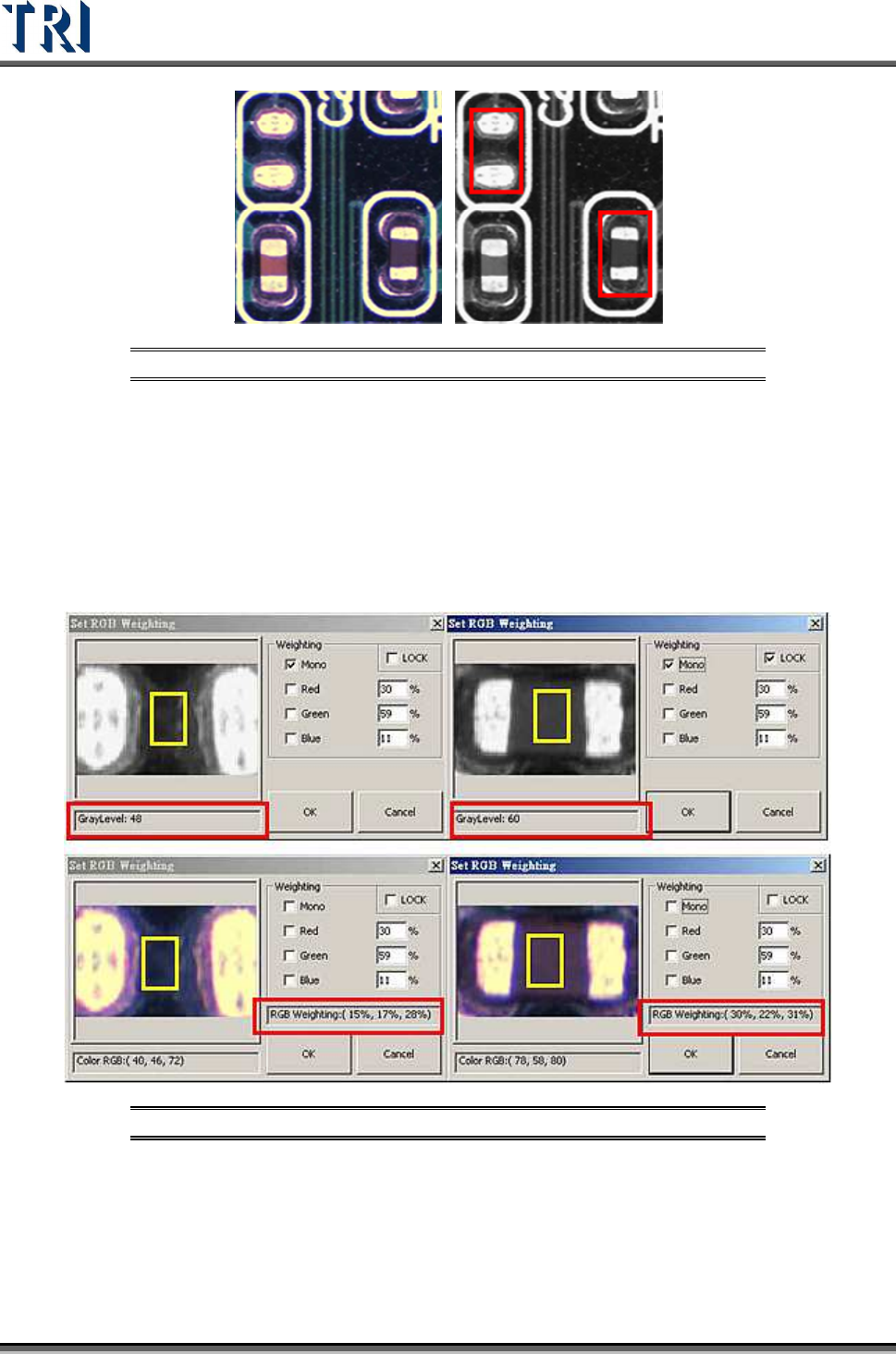
Figure 397: Missing Designator: Color (left) & Monochrome Images
In the top-left figure below a missing designator has a gray level of 48. The top-right shows a
placed designator with a gray level of 60, which is very close to the missing designator. This
will cause unavoidable false calls or missed calls. These pictures were captured by a
monochrome camera, where the gray level is analyzed within the yellow box.
The two pictures on the bottom are captured by the 3 CCD True Color Camera. The RGB
weighting ratios within the yellow boxes are: RGB (15%, 17%, 28%) for a missing designator,
and RGB (30%, ,22%, 31%) for a placed designator.
Figure 398: Monochrome (above) vs. RGB Values
According to the compared figures above, the Red value makes the most value difference.
Therefore, use the RGB Color Weighting to make a better contrast between the two by
raising Red percentage ratio up to 200. A much bigger gray level contrast will be visible
between the two pictures after raising the Red ratio value and lowering the Blue and the
Green values.
Test Research Inc.
TR7500 Series User Guide –Software v.2.9.0 239
In general, the RGB Weighting function may reinforce the result of the color reflection of
components, making a better contrast during the inspection. The RGB Weighting method will
tremendously reduce false calls and missed calls. This method is called the “Color Check
Method” (CCM).
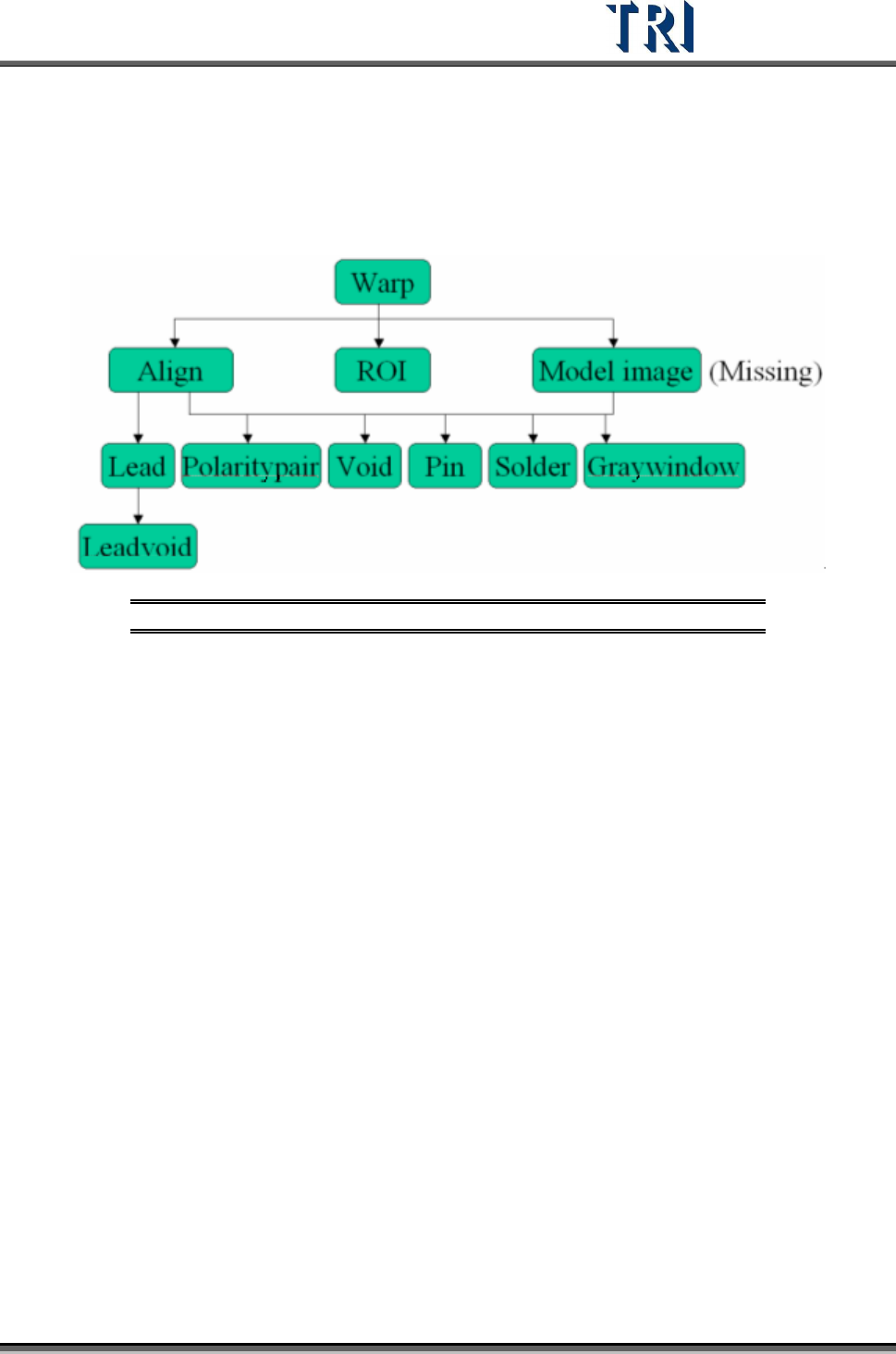
9.4 Structure of Inspection Boxes
Figure 399: Inspection Box Structure
Inspection boxes lying in the upper level can be used to locate an inspection box in a lower
level.
Test Research Inc.
240 TR7500 Series User Guide –Software v.2.9.0
10 P
RINCIPLES FOR
SPECIAL
P
LANE
10.1 Irregular Panel
If the panel is irregular, that is we can’t explain it by MxN, we have to program by the
following steps.
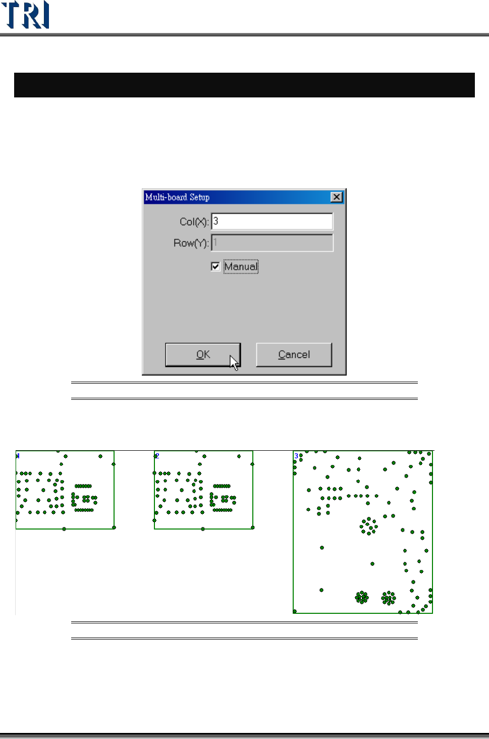
Step1. Load a CAD file. Load one of the CADs file first.
Step2. Set the number of boards, and select [Manual].
Figure 400: Set Number of Boards for Irregular Panel
Step3. Right click on the board except Board 1 and select [Load CAD] to load the other
CADs.
Figure 401: Load CADs
Step4. Calculate the rotate angle by finding 2 components in Board 1.
Step5. Locate the boards except Board 1.
Step6. Set the panel size.
Step7. Do the following standard steps.