TR7500_Series_Software_v29_En - 第262页
Test Research Inc. 240 TR7500 Series User Guid e –Softwa re v.2.9.0 10 P RINCIP LES F OR SPECIAL P LANE 10.1 Irreg ular Panel If the panel is irre gular, that is we can’ t explai n it by MxN, we hav e to program by the f…
Test Research Inc.
TR7500 Series User Guide –Software v.2.9.0 239
In general, the RGB Weighting function may reinforce the result of the color reflection of
components, making a better contrast during the inspection. The RGB Weighting method will
tremendously reduce false calls and missed calls. This method is called the “Color Check
Method” (CCM).
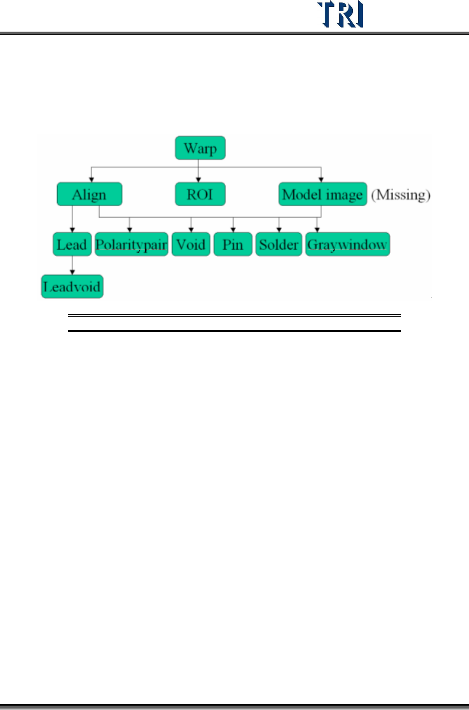
9.4 Structure of Inspection Boxes
Figure 399: Inspection Box Structure
Inspection boxes lying in the upper level can be used to locate an inspection box in a lower
level.
Test Research Inc.
240 TR7500 Series User Guide –Software v.2.9.0
10 P
RINCIPLES FOR
SPECIAL
P
LANE
10.1 Irregular Panel
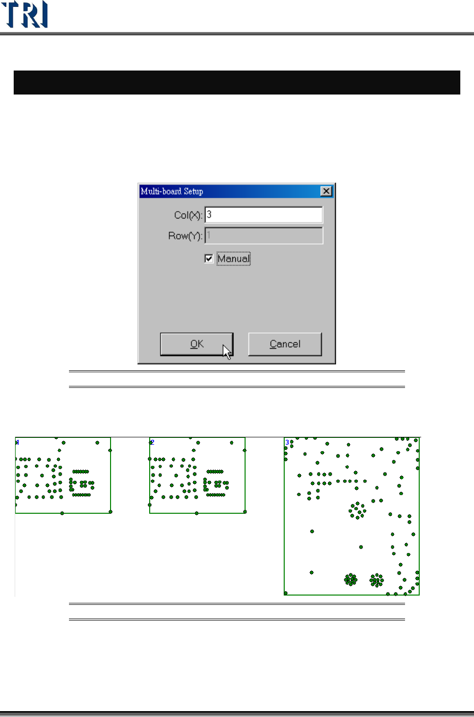
If the panel is irregular, that is we can’t explain it by MxN, we have to program by the
following steps.
Step1. Load a CAD file. Load one of the CADs file first.
Step2. Set the number of boards, and select [Manual].
Figure 400: Set Number of Boards for Irregular Panel
Step3. Right click on the board except Board 1 and select [Load CAD] to load the other
CADs.
Figure 401: Load CADs
Step4. Calculate the rotate angle by finding 2 components in Board 1.
Step5. Locate the boards except Board 1.
Step6. Set the panel size.
Step7. Do the following standard steps.
Test Research Inc.
TR7500 Series User Guide –Software v.2.9.0 241
10.2 Combine the CADs with different origin
For a panel without complete CAD file, it has to be combined by several CAD files, When the
several CAD files are with different origins, user could use this function to combine the CAD
files and export the combined AOI file. Then user could use this AOI file to program.
Step1. Load CAD file. Load one of the CADs file first.
Step2. Input the number of the CAD files that you want to combine. And select [Manual].
Figure 402: Set Number of Boards for Irregular Panel
Step3. Right click on the board except Board 1 and select [Load CAD] to load the other
CADs.
Step4. Calculate the rotate angle by finding 2 components in Board 1.
Step5. Locate the boards except Board 1.
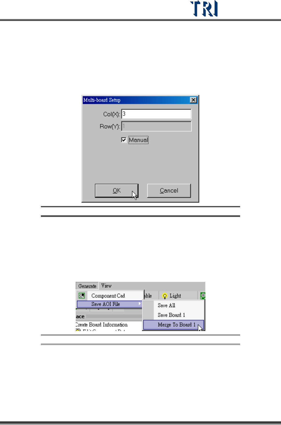
Step6. Export the combined CAD file to an AOI file. Select [Generate/Merge to Board 1] to
save the file.
Figure 403: Save AOI File
Step7. Create a new program and load the new CAD file to do programming.
10.3 Change the multi-board layout
This function is to change the multi-board layout for a finished program. The rotate angel of
all boards in the panel has to be 180 degree rotation or the same with the original board.