TR7500_Series_Software_v29_En - 第264页
Test Research Inc. 242 TR7500 Series User Guid e –Softwa re v.2.9.0 Step1. Open a finished pro g ram. Step2. Enter [ATPG/Gener t e Multibo ard CAD Data]. Step3. Select [Set/Edit M ode] Figure 404 : Set Step4. Right click…
Test Research Inc.
TR7500 Series User Guide –Software v.2.9.0 241
10.2 Combine the CADs with different origin
For a panel without complete CAD file, it has to be combined by several CAD files, When the
several CAD files are with different origins, user could use this function to combine the CAD
files and export the combined AOI file. Then user could use this AOI file to program.
Step1. Load CAD file. Load one of the CADs file first.
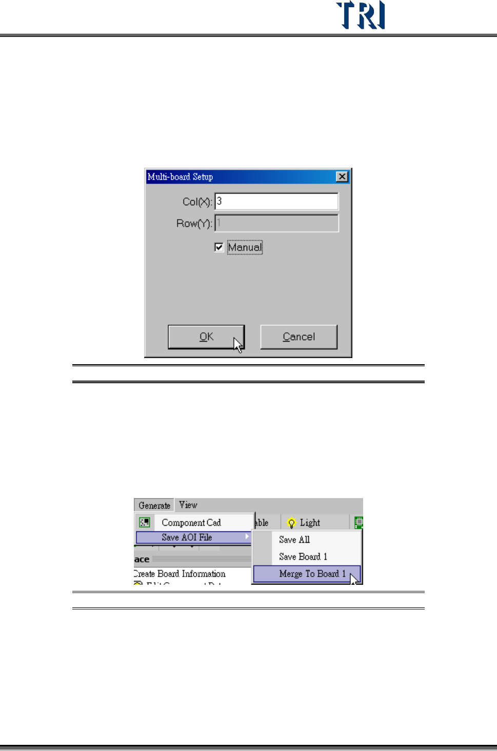
Step2. Input the number of the CAD files that you want to combine. And select [Manual].
Figure 402: Set Number of Boards for Irregular Panel
Step3. Right click on the board except Board 1 and select [Load CAD] to load the other
CADs.
Step4. Calculate the rotate angle by finding 2 components in Board 1.
Step5. Locate the boards except Board 1.
Step6. Export the combined CAD file to an AOI file. Select [Generate/Merge to Board 1] to
save the file.
Figure 403: Save AOI File
Step7. Create a new program and load the new CAD file to do programming.
10.3 Change the multi-board layout
This function is to change the multi-board layout for a finished program. The rotate angel of
all boards in the panel has to be 180 degree rotation or the same with the original board.
Test Research Inc.
242 TR7500 Series User Guide –Software v.2.9.0
Step1. Open a finished program.
Step2. Enter [ATPG/Generte Multiboard CAD Data].
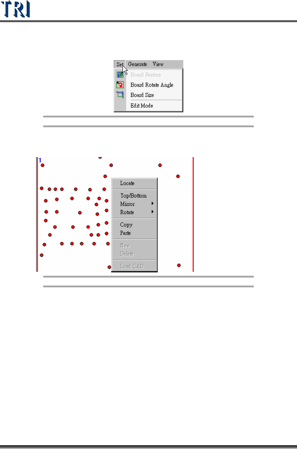
Step3. Select [Set/Edit Mode]
Figure 404: Set
Step4. Right click on the picture and select New or Delete a column or row.
Figure 405: Right-Clicking to New or Delete a Column or Row
Step5. After setting the number and the rotate angle of multi-board, do the following
standard process to program.
(1)
Find rotate angle.
(2)
Set Board 1 Size
(3)
Find Fiducial Mark
(4)
Skip [Merge], press [Next] to do FOV arrangement. Now system will copy the
parameters of Board 1 to the other boards.
(5)
Capture FOV image and Relocate inspection boxes.
(6)
After finishing ATPG, user has to select [Utilities/Capture Panel Map].
10.4 Different Gaps within multi-boards
When the cap between boards are not the same, (for example, many panels are put on a
carrier, user can use this function to create the correct multi-board information.
Step1. Set multi-board layout (MxN)
Test Research Inc.
TR7500 Series User Guide –Software v.2.9.0 243
Step2. Find the rotate angle.
Step3. Locate the first Block to get the gap of X direction and Y direction within Block.
Step4. Select Block 2 and Block 3 by pressing [Shift] key and left clicking on the board.
Locate the board to get the gap between Blocks.
Step5. Press [Next] and do the other standard process in ATPG.
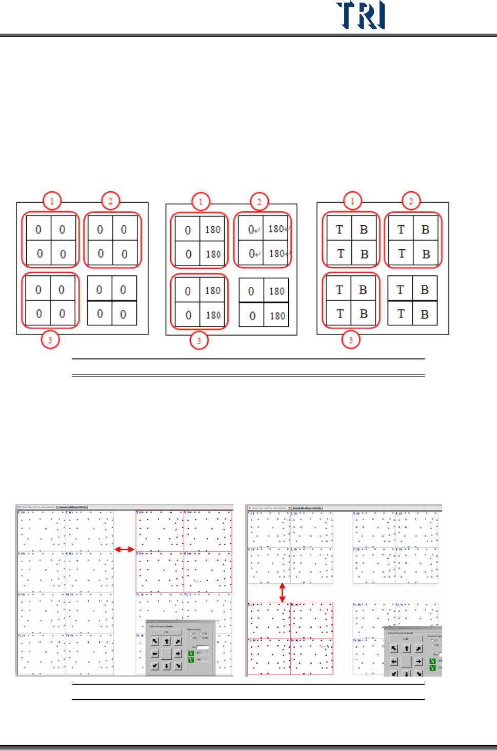
There are three main types for multi-boards, explained below.
Type 1 Type 2 Type3
Figure 406: Types of Panel Layout
Type 1
(1) Locate the Board 6 to get the gap between boards.
(2) Select the multi-boards in Block 2 by [Shift], then locate a component in Block 2 to get
the X direction gap between Blocks.
(3) Select the multi-boards in Block 3 by [Shift], then locate a component in Block 3 to get
the Y direction gap between Blocks.
Figure 407:Type 1
X-Gap
Y-Gap