TR7500_Series_Software_v29_En - 第269页
Test Research Inc. TR7500 Series User Guide – Software v.2.9.0 247 11.5 Capture FO V Select [Capture FOV ] page then it display s the FOV image that the syste m captured be f ore. If the chosen componen t t ype has di ff…
Test Research Inc.
246 TR7500 Series User Guide –Software v.2.9.0
11.2 Train Dialog
Press
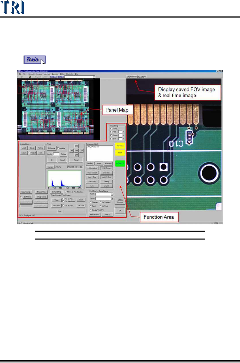
to enter the [Train] dialog. The screen shown below will appear.
Figure 411: Train Dialog Screen
11.3 Board View
The positions of FOVs (fields of view) are displayed here. Select the camera position to
review.
Red boxes refer to the top camera FOVs. Yellow boxes signify the front camera FOVs.
Orange boxes are for the rear camera FOVs. Purple boxes mean The left and right camera
FOVs are shown in purple and blue, respectively. The green box is the current FOV.
Click on the FOV area and the [Real-Time Image] and [Saved FOV Image] will change to the
selected FOV.
11.4 Real FOV
Select [Real FOV] page then it displays the real time image. Click on the panel map or right
click on the image to move the camera to capture the image.
Test Research Inc.
TR7500 Series User Guide –Software v.2.9.0 247
11.5 Capture FOV
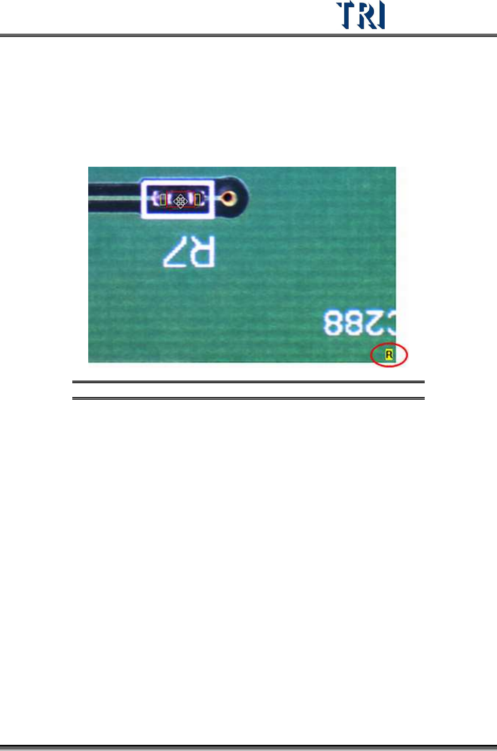
Select [Capture FOV] page then it displays the FOV image that the system captured before.
If the chosen component type has different groups, the group of the component that is
chosen will be shown at the lower right corner.
Figure 412: Component Groups Shown in Bottom Right
Test Research Inc.
248 TR7500 Series User Guide –Software v.2.9.0
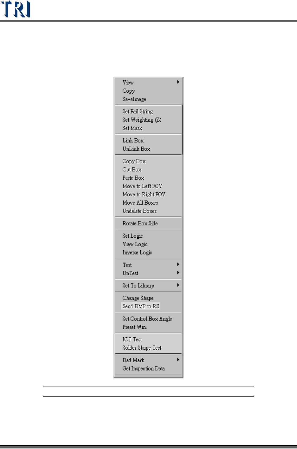
11.6 Tools
Right click on the image to show the tools.
Figure 413: Tools Menu Commands