TR7500_Series_Software_v29_En - 第278页
Test Research Inc. 256 TR7500 Series User Guid e –Softwa re v.2.9.0 Figure 428 : Set Bad Mark - 1 2. Right click mouse to add a [Bad Mark] Figure 429 : Bad Mark Dial og 3. Select the board number 4. The [Bad Mark] wi ll …
Test Research Inc.
TR7500 Series User Guide –Software v.2.9.0 255
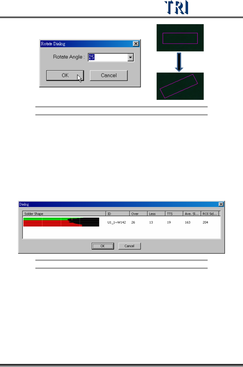
Figure 426: Rotate Control Bo Process
11.6.26 Present Win
The control box will move to the center using the default size.
11.6.27 ICT Test
Forces a component to be tested by ICT.
11.6.28 Solder Shape Test
Display the solder inspection analyst result, as shown in the following figure. Only for the
TR7500 series.
Figure 427: Display Solder Shape
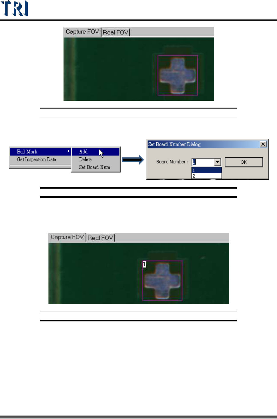
11.6.29 Bad Mark
Under [Train] users may right-click the mouse to add bad marks in an FOV. The system will
detect the bad mark each time, and the board will be labeled as [Skip] once the bad marks
fail. For more than one bad mark on the board, any of the bad marks will result in the board
labelled as [Skip]. Setting a bad mark will not decrease the inspection cycle time.
1. Move the control box on the taget point to set as a [Bad Mark].
Test Research Inc.
256 TR7500 Series User Guide –Software v.2.9.0
Figure 428: Set Bad Mark - 1
2. Right click mouse to add a [Bad Mark]
Figure 429: Bad Mark Dialog
3. Select the board number
4. The [Bad Mark] will show the board number inside of inspection box
Figure 430: Set Bad Mark - 2
5. Users may change the search range, image, and parameters of a [Bad Mark].
6. Under [Train] window, users may search for a [Bad Mark] by using [Find FOV by
Type/Name] and selecting [Bad Mark] under [Type].
7. Users may change the [Bad Mark] inspection box to inverse logic by right-clicking the
mouse on the inspection box and selecting [Inverse Logic].
Test Research Inc.
TR7500 Series User Guide –Software v.2.9.0 257
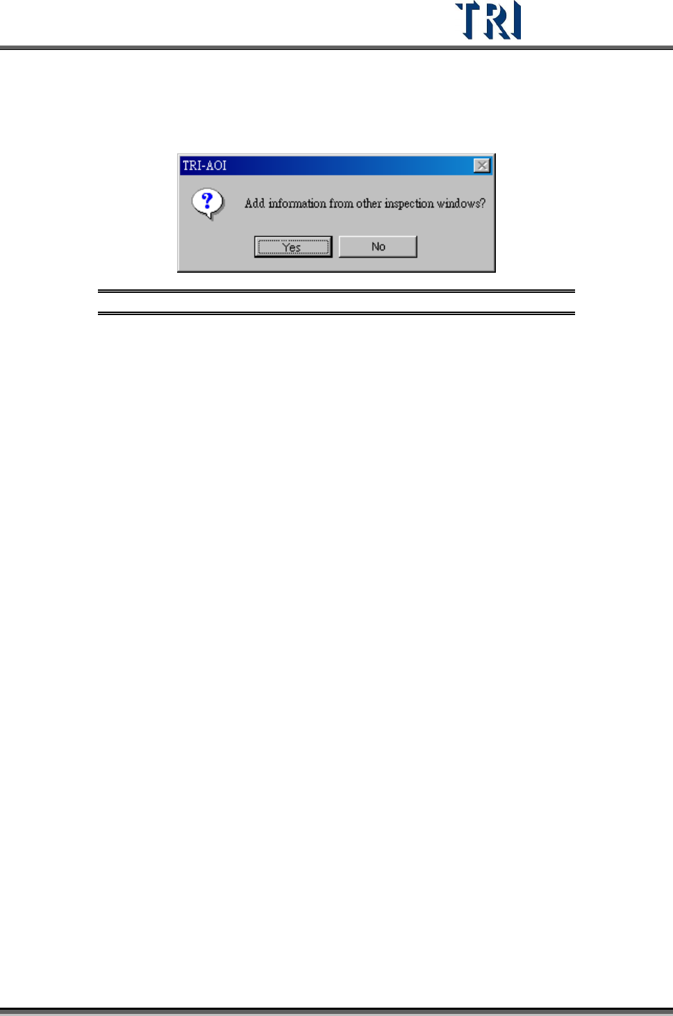
11.6.30 Get Inspection Data
For an untest [Missing] window, users can use this function to import alternative images with
the same type as this window.
Figure 431: Get Inspection Data Dialog