TR7500_Series_Software_v29_En - 第318页
Test Research Inc. 296 TR7500 Series User Guid e –Softwa re v.2.9.0 Figure 489 : Confirm Save C onveyor Width 13.4 Width Load ing 1. W hen openi ng a existin g project, the system shows the dialo g below asking to use th…
Test Research Inc.
TR7500 Series User Guide –Software v.2.9.0 295
13 A
UTO
-C
ONVEYOR
W
IDTH
This procedure requires the auto conveyor width module.
13.1 Hardware
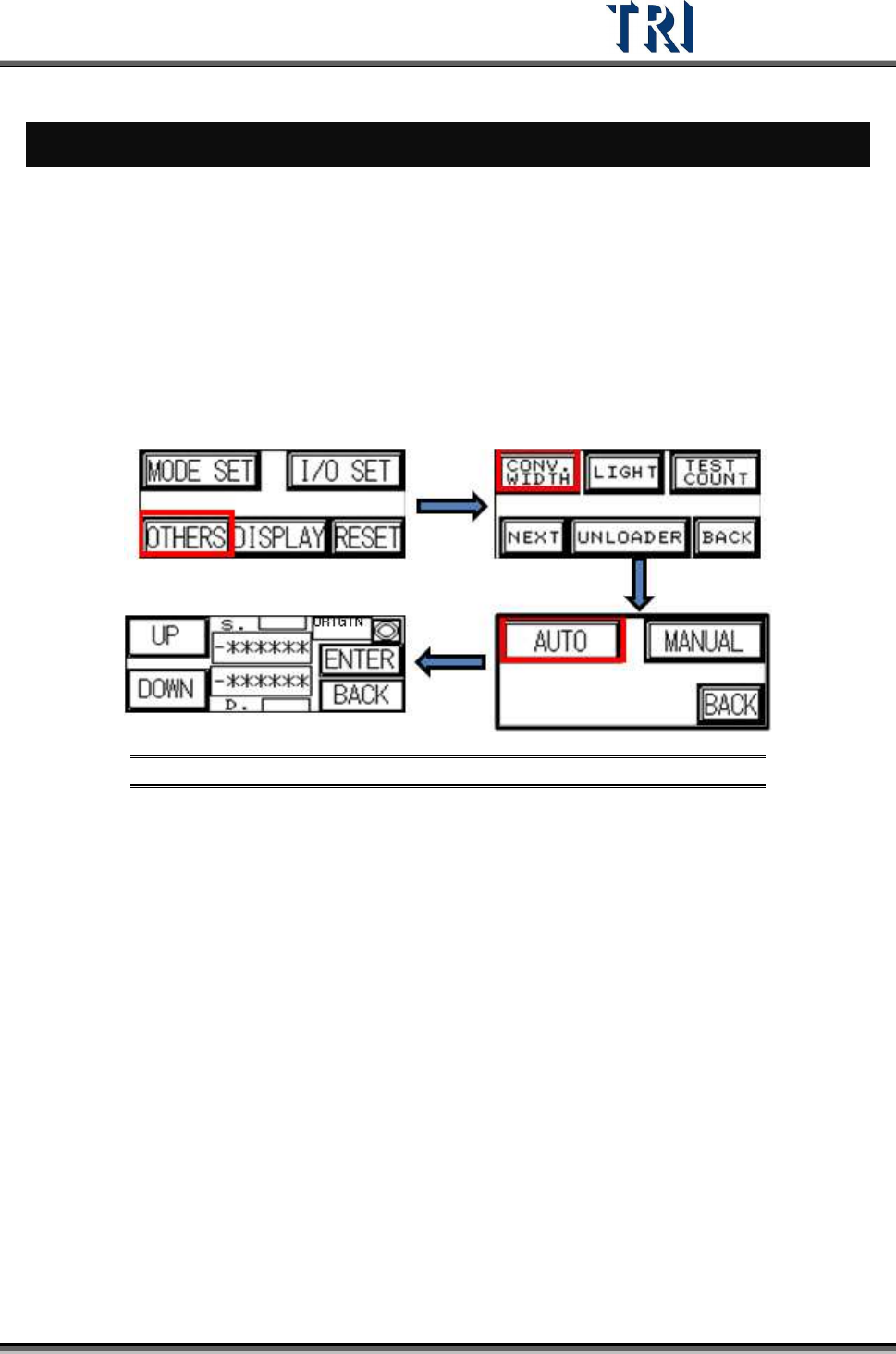
1. Open the auto conveyor adjustment function on the HCI (refer to TR7500 User Guide –
Hardware).
2. Referring to the figure below, press [AUTO] then the conveyor will go to the original
position. Then press [UP] or [DOWN] to enlarge or reduce the conveyor width. When
finished, press [Enter] to save the data. Then press [Back] to go back to the stand-by
image.
Figure 488: Use HCI to Set Conveyor Width
13.2 Software Setting
1. The Windows version of the PC must be compatible with the auto conveyor width system.
2. In the Windows Registry, add a DWORD [AutoConveyorWidth] with the value = [1]
13.3 Saving Width Data to Project
1. Adjust the conveyor width with [Auto Conveyor] Function.
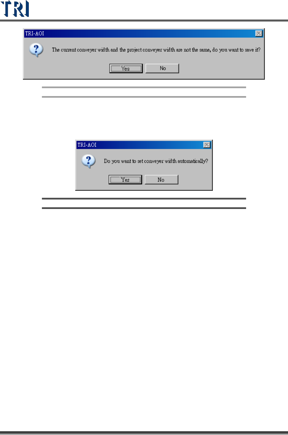
2. When saving the project, the system saves the width to the project automatically.
3. If the current width is not the same with the width in project, system shows the dialog
below asking to replace the saved width with current width.
Test Research Inc.
296 TR7500 Series User Guide –Software v.2.9.0
Figure 489: Confirm Save Conveyor Width
13.4 Width Loading
1. When opening a existing project, the system shows the dialog below asking to use the
saved width.
Figure 490: Confirm Auto-Set Conveyor Width
2. When select [Yes], the system starts to adjust the conveyor width; If there is a board on
the conveyor, remove the board first. If [No] is selected, the system does not perform any
action.
3. If no data was saved in the project before, none of the above requests will be made.
Test Research Inc.
TR7500 Series User Guide –Software v.2.9.0 297
14
S
TART TO
I
NSPECT
WARNING: Risk of electric shock and mechanical injury. Only fully trained
persons should be allowed to perform the installation process.
14.1 Power On
1. Open the upper cover and confirm that there is no foreign matter inside. Be sure the front
and back emergency stop switches are released, and the interlock is set to [ON]. Then
close the upper cover.
2. Be sure that the power cable is connected to 220V single phase power.
3. Turn on the breaker that is on the back door.
4. Turn on the power switch clockwise to start the machine.
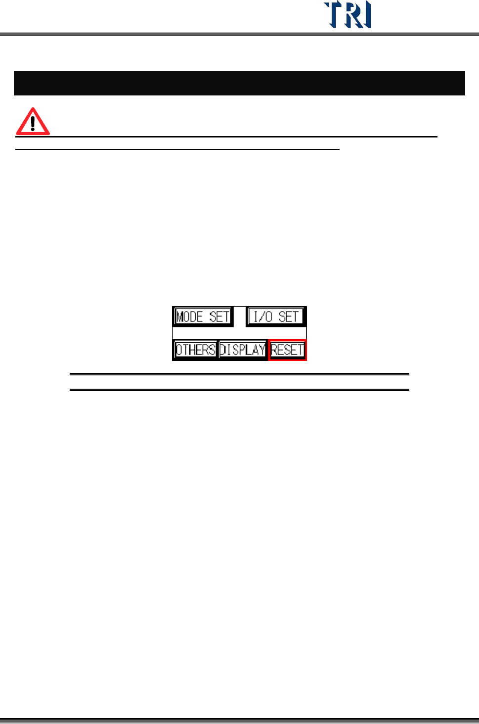
5. Press [RESET] on the HCI to start the X-Y table.
Figure 491: Push Reset on HCI to Start X-Y Table
14.2 Open Program
1. Double click on the shortcut of the TR7500 main program.
2. Open a project file (*.pre)